
Part gripping device with self-checking function

A technology for grasping devices and parts, applied in manipulators, program-controlled manipulators, manufacturing tools, etc., can solve problems such as delayed work progress, unstable gripping, and lack of fault self-checking capabilities of the grasping device, and achieve stable grasping. Effect

Inactive Publication Date: 2016-07-06
CHENGDU BEISEN WEIREN TECH CO LTD
View PDF9 Cites 2 Cited by
  • Summary
  • Abstract
  • Description
  • Claims
  • Application Information

AI Technical Summary

Problems solved by technology

Traditional industrial machine processing uses a fixed processing trajectory, which has poor adaptability. Due to changes in environmental parameters, such as equipment failures, accumulated movement errors, tool wear, solder changes, and subtle changes in part materials, even if the robot repeats the movements accurately, it is still impossible to avoid waste products. For the processing of high-value workpieces, once there is waste, the loss will be huge
Moreover, the existing grabbing device can only grab a single type of parts. Once the parts are too large, the gripping will be unstable. The failure cannot be repaired in time, which delays the work progress

Method used


Image

  • Part gripping device with self-checking function

Examples


Embodiment 1

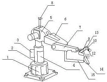
[0018] Such as figure 1 As shown, the present invention includes a base 1, and also includes a support member 2 installed on the base 1, a first arm 5, a second arm 6, a third arm 7, a grasping claw 9, a tray 14 and an auxiliary arm 15, The first arm 5, the second arm 6 and the third arm 7 are sequentially connected in series, and one end of the first arm 5 is also installed on the top of the support member 2, and one end of the third arm 7 is also connected with a grasping claw 9; The inside of described support member 2 is also provided with interconnected controller 4 and acquisition card, motor 3 is also installed on the outer wall of support member 2, camera 8 is also installed on the top of first arm 5, motor 3, camera 8 and the second The three arms 7 are all connected to the controller 4; the grabbing claw 9 is provided with a sliding grabbing plate 10 and a chute 11, and the sliding grabbing plate 10 can slide back and forth on the chute 11, at the bottom of the third...

Embodiment 2

[0021] This embodiment is preferably as follows on the basis of Embodiment 1: a layer of sponge is arranged inside the tray 14 . The setting of the sponge inside the tray can provide a buffer force on the contact surface between the large parts and the tray, avoiding collisions between the parts and the tray, resulting in damage to the parts.

[0022] A plurality of anti-slip blocks 12 are also arranged on the inner wall of the sliding grab board 10 . With the anti-slip fast setting, the friction between the gripping claw and the parts can be increased, further preventing the parts from slipping during the grabbing process, and preventing the parts from being damaged during the grabbing process.

[0023] The camera 8 can rotate at any angle of 360°. The design of the camera can facilitate the camera to adjust the angle to take pictures of parts with the best angle.

[0024] A plurality of ventilation holes are also provided on the side of the support member 2 . The ventilat...


PUM


Abstract

The invention discloses a component grabbing device with a self-checking function, which includes a base, and also includes a supporting part installed on the base, a first arm, a second arm, a third arm, grabbing claws, a tray and an auxiliary arm , the first arm, the second arm and the third arm are sequentially connected in series, and one end of the first arm is also installed on the top of the support component; the inside of the support component is also provided with a controller and an acquisition card connected to each other, the motor, Both the camera and the third arm are connected to the controller; a sliding grabbing plate and a chute are set on the grabbing claw, the sliding grabbing plate can slide back and forth on the chute, and the auxiliary arm is also movably connected at the bottom of the third arm , the extended end of the auxiliary arm mounts the tray. Through the above-mentioned structure, the present invention can realize firm grasping of large parts and flexible use, and at the same time, when the device works abnormally, it can automatically remind the staff and perform maintenance in time to ensure that the device can quickly resume work.

Description

technical field [0001] The invention relates to the processing field, in particular to a component grabbing device with a self-checking function. Background technique [0002] Industrial robots can meet the needs of today's industrial cost and time efficiency, as well as the flexibility of material processing. With their advantages of high efficiency, low cost, and good flexibility, they can be used as automated processing equipment to replace traditional machining units. In recent years, compared with CNC machining centers, FMC and other processing equipment, industrial robots used in the field of mechanical processing have the advantages of low cost, high degree of automation, good flexibility, small installation space, etc., and can adapt to multi-variety, small batch, on-site processing It can meet the complex processing requirements such as free-form surfaces and complex cavities. Traditional industrial machine processing uses a fixed processing trajectory, which has p...

Claims


Application Information

Patent Timeline
Patent Type & Authority Applications(China)
IPC IPC(8): B25J9/16B25J19/02B25J19/06
CPCB25J9/1697B25J19/023B25J19/061
Inventor 张楠魏艾
Owner CHENGDU BEISEN WEIREN TECH CO LTD
Learn More