
A scale damping line

A technology of damping wires and scales, applied in the field of damping wires, can solve problems such as the complexity of anti-vibration devices, achieve outstanding anti-vibration performance, avoid damage or broken strands, and facilitate installation and maintenance

Active Publication Date: 2017-09-01
STATE GRID CORP OF CHINA +1
View PDF4 Cites 0 Cited by
  • Summary
  • Abstract
  • Description
  • Claims
  • Application Information

AI Technical Summary

Problems solved by technology

Therefore, anti-vibration devices for large-span ground wires are usually more complicated and require special research and design

Method used


Image

  • A scale damping line
  • A scale damping line
  • A scale damping line

Examples


Embodiment 1

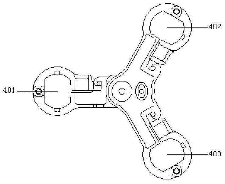
[0051] The first side damping line clamp 1 is installed at a place 1m away from the outlet of the suspension line clamp guard line or the tension line clamp of the fixed overhead line 3, one end of the first damping line 2 is installed on the first side damping line clamp 1, and the other One end is connected to the second chuck 402 of the first scale damping wire clamp 4, and the first chuck 401 of the first scale damping wire clamp 4 is clamped on the overhead wire 3. At this time, the second chuck 402 and the second The three chucks 403 are located on the same horizontal plane. The first collet 401 of the first scale damping wire clamp 4 is tightly locked on the overhead wire 3 by the first wire clamp gland 405 by the stop pin 406, and the damping wire is nested in the chuck holding groove of the wire clamp, and then The clamping cover is locked tightly by a stop pin.

[0052] One end of the second damping wire 2 is connected to the third clip 403 of the first scale dampin...

Embodiment 2

[0057] The first side damping line clamp 1 is installed 1m away from the outlet of the suspension line clamp guard line or the tension line clamp of the fixed overhead line 3, and one end of the first damping line 2 is installed on the first side damping line clamp 1, The other end is connected to the third clamp 403 of the first scale damping wire clamp 4, wherein the second clamp 402 of the first scale damping wire clamp 4 is clamped on the overhead wire 3, and the first clamp 401 It is located on the same level as the third chuck 403 .

[0058] One end of the second damping wire 2 is connected to the first clip 401 of the first scale damping wire clamp 4, and the other end is fixedly connected to the third clamp 403 of the second scale damping wire clamp 4 on the same side, namely The second damping line 2 and the first damping line 2 are respectively located on opposite sides of the overhead line 3 . The second scale damping wire clamp 4 is clamped on the overhead wire 3 ...


PUM


Abstract

A musical scale type damping wire (2), used for preventing an overhead wire (3) in an overhead power transmission line from vibrating due to breezes. The musical scale type damping wire comprises lateral damping wire clamps (1) and musical scale damping wire clamps (4) respectively arranged on the overhead wire. The lateral damping wire clamps are fixedly arranged at two ends of the overhead wire respectively, the musical scale damping wire clamps are arranged between the lateral damping wire clamps at intervals, and damping wires are arranged between each lateral damping wire clamp and an adjacent musical scale damping wire clamp and between every two musical scale damping wire clamps respectively. The musical scale type damping wire stably holds a conductor, thereby avoiding the damage or strand breakage of the conductor due to an excessively high pressure, and can meet vibration control requirements on low, medium and high frequencies of a conductor / ground wire / optical fibre composite overhead ground wire OPGW in an over-35 kV power transmission line, in particular, in an ultra-high-voltage power transmission line. The vibration control coverage frequency is wide, the energy consumption effect is remarkable, and the vibration control effect is prominent.

Description

technical field [0001] The invention relates to a damping wire, in particular to a scale-type damping wire used for preventing overhead transmission line conductor / ground wire / OPGW breeze vibration. Background technique [0002] Breeze vibration is one of the important factors that threaten the safe operation of UHV transmission lines, and it is a problem that the line design, construction and operation management departments must attach great importance to. Long-term breeze vibration can easily lead to damage or even failure of each component of the transmission line (ground wire, hardware, etc.), which seriously threatens the safe operation of the transmission line. Therefore, effective measures must be taken to prevent and control the breeze vibration of the guide (ground) wire and the OPGW. The anti-vibration of guide (ground) wire and OPGW is usually realized by selecting and installing appropriate anti-vibration devices based on factors such as vibration form, occurre...

Claims


Application Information

Patent Timeline
Patent Type & Authority Patents(China)
IPC IPC(8): H02G7/14
CPCH02G7/14
Inventor 王景朝高渊万建成尹泉刘臻曹道珍齐翼
Owner STATE GRID CORP OF CHINA
Learn More