
Formation pressure calculation method

A technology of formation pressure and calculation method, applied in calculation, earthwork drilling, special data processing application, etc.

Inactive Publication Date: 2016-06-29
SINOPEC SHENGLI PETROLEUM ENG CO LTD DRILLING TECH RES INST
View PDF5 Cites 3 Cited by
  • Summary
  • Abstract
  • Description
  • Claims
  • Application Information

AI Technical Summary

Problems solved by technology

[0003] The purpose of the present invention is to overcome the existing technical defects, and provide a method for calculating formation pressure when gas drilling encounters high-yield gas flow or blowout and cannot be shut down; Provide basis for well scheme design and construction

Method used


Image

  • Formation pressure calculation method
  • Formation pressure calculation method
  • Formation pressure calculation method

Examples


Embodiment Construction

[0034] Attached below figure 1 And attached figure 2 The present invention is further described:

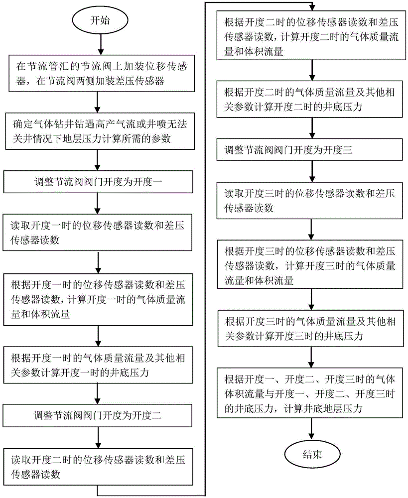
[0035] like figure 1 As shown, the calculation method of the formation pressure in the case of gas drilling encountering high-yield gas flow or blowout and unable to shut down the well includes the following steps:

[0036] 1. Install a displacement sensor on the choke valve of the choke manifold, and install a differential pressure sensor on both sides of the choke valve.

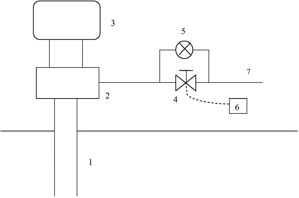
[0037] like figure 2 As shown, before spud, a displacement sensor 6 is installed on the throttle valve 4 on the discharge pipeline 7, and a differential pressure sensor 5 is installed on both sides of the throttle valve 4, and the differential pressure sensor 5 is installed as close to the throttle valve 4 as possible.

[0038] 2. Determine the parameters required for formation pressure calculation when gas drilling encounters high-yield gas flow or blowout cannot shut down the well.

[0039] Determine...


PUM


Abstract

The invention discloses a formation pressure calculation method. The method mainly comprises the following steps: additionally mounting a displacement sensor on a throttle valve of a throttle manifold, and additionally mounting a differential pressure sensor on two sides of the throttle manifold; calculating parameters required for formation pressure calculation; adjusting the opening degree of the throttle valve to be at least three different opening degrees; reading a read number of the displacement sensor and a read number of the differential pressure sensor under the condition of each opening degree; calculating gas mass flow and volume flow under the condition of each opening degree; calculating a bottom hole pressure under the condition of each opening degree; and according to the gas volume flow under the condition of at least three different opening degrees and the bottom hole pressure under the condition of the corresponding opening degrees, calculating a bottom hole formation pressure. According to the method, the formation pressure under the condition that a well cannot be closed due to the fact that gas drilling encounters high gas flow or blowout can be determined, thereby providing a basis for subsequent construction scheme making and well killing method selection; and the method is suitable for field use.

Description

technical field [0001] The invention belongs to the technical field of formation pressure detection in oil and gas development, and relates to a method for calculating formation pressure when a gas drilling encounters a high-yield gas flow or a blowout fails to shut down the well. Background technique [0002] During the drilling process, due to factors such as complex downhole conditions and insufficient understanding of geological conditions, the formation and formation fluid are unpredictable during the drilling process, and well kicks or even blowouts are prone to occur during the drilling process. After a blowout occurs, it is necessary to kill the well in time. During the well killing process, the formation pressure is the key parameter for the well killing. Once the formation pressure is determined, the killing fluid density, well killing displacement and other related killing parameters can be optimally designed. When gas drilling encounters high-yield gas flow or bl...

Claims


Application Information

Patent Timeline
Patent Type & Authority Applications(China)
IPC IPC(8): E21B47/06G06F19/00
Inventor 宋荣荣陈永明曹强李晓燕修良王树江朱焕刚公培斌赵鹏许强许萍
Owner SINOPEC SHENGLI PETROLEUM ENG CO LTD DRILLING TECH RES INST
Learn More