A chain protection mechanism and a crawler walking device

A technology for guard chain and crawler chain, which is applied in the directions of crawler vehicles, motor vehicles, transportation and packaging, etc., can solve the problems of reducing the service life of guard plates, wear of guard plates, derailment, etc.

Inactive Publication Date: 2019-07-16
泉州市泉永机械发展有限公司
View PDF6 Cites 0 Cited by
  • Summary
  • Abstract
  • Description
  • Claims
  • Application Information

AI Technical Summary

Problems solved by technology

[0002] As known, the crawler belt traveling device mainly includes a trolley frame (crawler frame), a driving sprocket, a guide wheel, a crawler belt, a supporting roller and a supporting sprocket, and the crawler belt is tensioned between each wheel through a chain rail, and is driven by the driving sprocket. For walking, the supporting rollers are set at the bottom of the trolley frame to transfer the weight of the machine to the track. During driving, it not only rolls along the chain track of the track, but also clamps the chain track to prevent it from sliding out laterally. , when turning, it will force the track to slide laterally on the ground, and the rollers restrict the chain rail through the flanges at both ends, but the height of the flange is low (small diameter), which is easy to cause derailment. In order to prevent the track derailment, it is necessary to install a chain protection mechanism on the trolley frame at the supporting wheel to limit the track. The existing chain protection mechanism mainly includes two parallel and opposite installation beams and two parallel and opposite installation beams connected between the two installation beams. The two guard plates are located at both ends of the rollers, and the rollers are located between the two installation beams. Due to the limitation of the track, the height of the guard plates is limited, and when the chain rail jumps on the flange of the rollers, it is easy to jump further. Derailment occurs due to passing through the guard plate. In addition, the existing guard plate is a cast-shaped plate structure. The guard plate will often contact with the chain rail, resulting in wear of the guard plate, which will cause damage to the guard plate for a long time and reduce the service life of the guard plate.

Method used


Image

  • A chain protection mechanism and a crawler walking device
  • A chain protection mechanism and a crawler walking device
  • A chain protection mechanism and a crawler walking device

Examples


Embodiment Construction

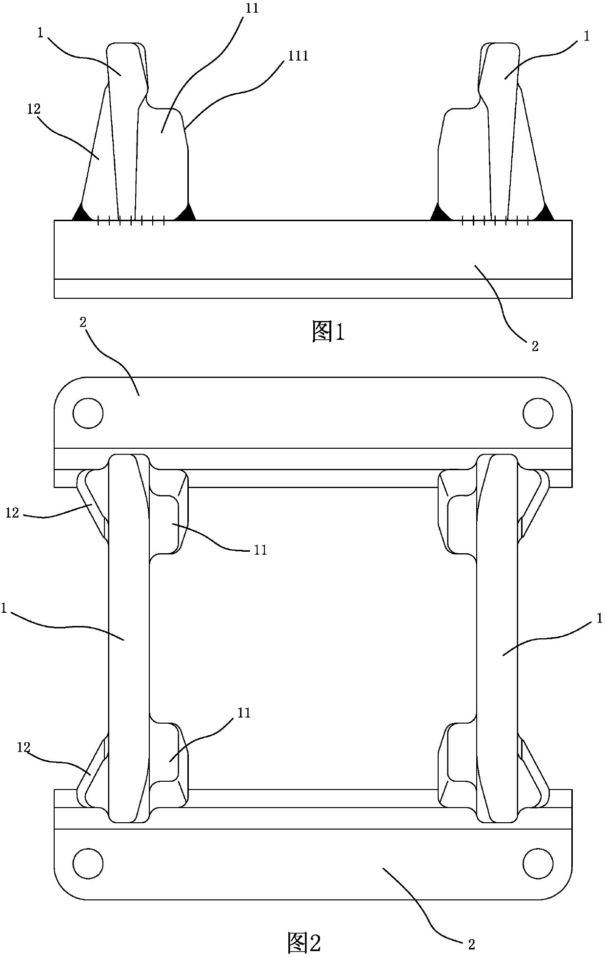
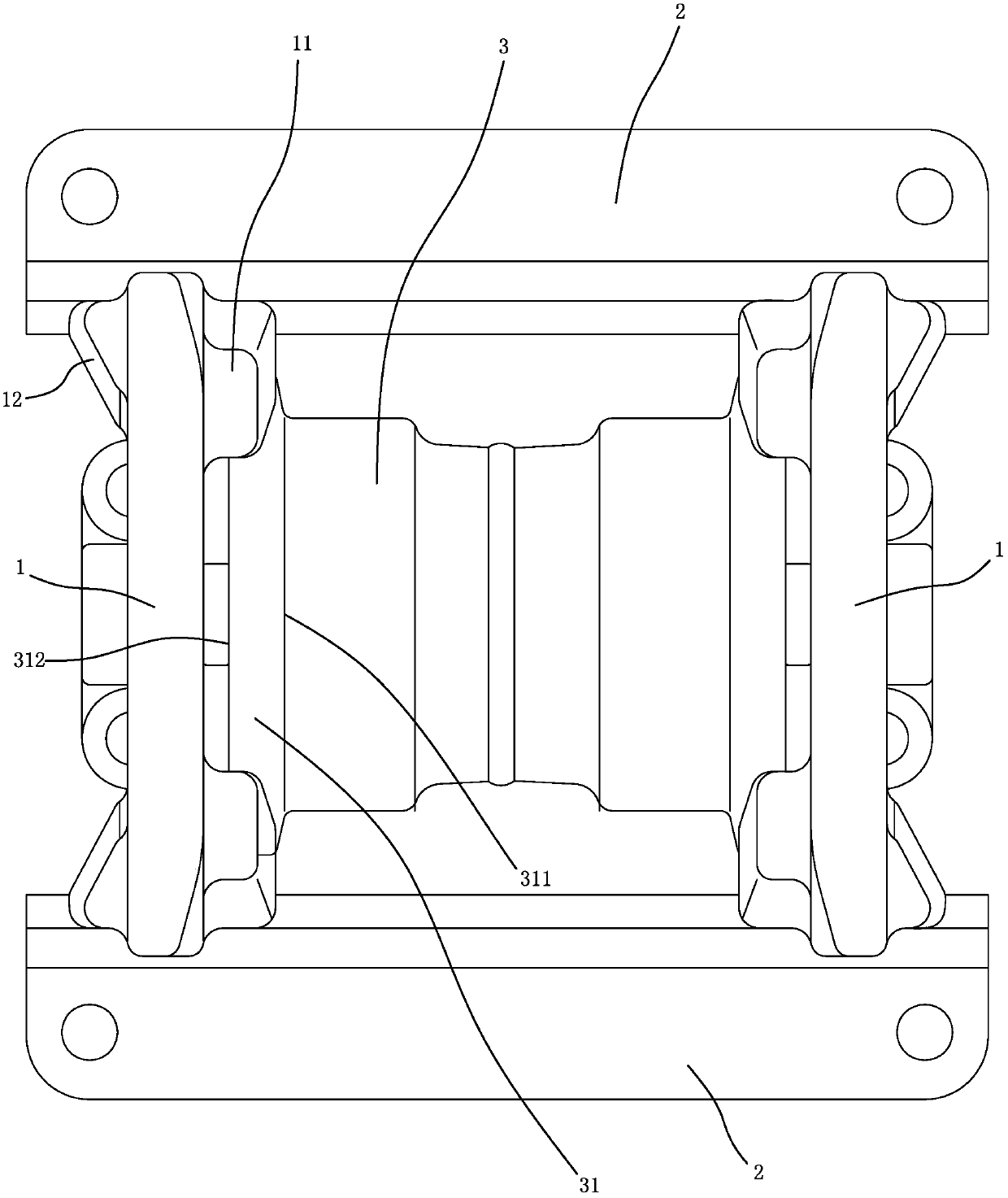
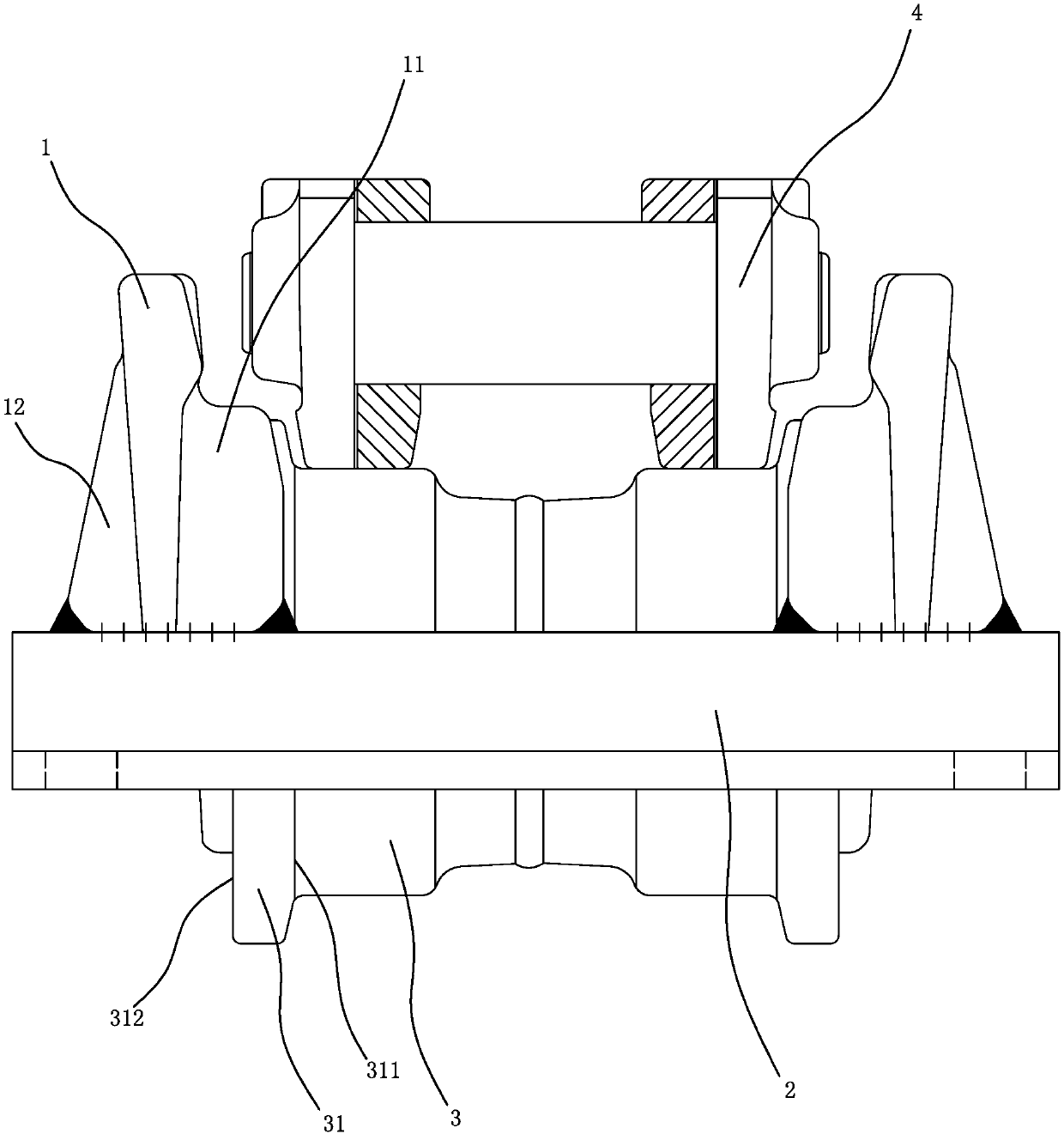
[0024] Refer to Figure 1 to Figure 5 As shown, a chain protection mechanism includes two mounting beams 2 and two guard plates 1 for preventing the crawler chain rail 4 from detaching from the roller 3 .

[0025] The supporting roller 3 is installed at the bottom of the track frame, and the two installation beams 2 are installed on the bottom of the track frame in parallel and opposite, and are located on both sides of the supporting wheel 3. On the outside of the flanges 31 at both ends of the roller 3, the track chain rail 4 is limited between the two guard plates 1 to be supported by the roller 3, and the opposite surfaces of the two guard plates 1 are respectively provided with flanges located on the roller 3 The two baffle plates 11 on both sides of 31, the upper end of the baffle plate 11 is higher than the top of the roller 3 flange 31 to prevent the track chain rail 4 from jumping up the roller flange 31, and the opposite sides of the two guard plates 1 are respective...


PUM


Abstract

The invention provides a protection chain mechanism and a caterpillar band walking device. The protection chain mechanism is used for preventing a chain track from being released from a supporting wheel and comprises two protection plates which are oppositely arranged on the outer sides of flanges at the two ends of the supporting wheel at interval, wherein a caterpillar band chain track is limited between the two protection plats and is supported by the supporting wheel; opposite surfaces of the two protection plates are provided with two stopping plates located on the two sides of the flanges of the supporting wheel respectively; and the upper ends of the stopping plates are higher than the tops of the flanges of the supporting wheel, so that a phenomenon that the caterpillar band chain track jumps onto the flanges of the supporting wheel, and further steps over the protection plates to leave away from the track can be prevented.

Description

technical field [0001] The invention relates to the field of crawler walking devices. Background technique [0002] As known, the crawler belt traveling device mainly includes a trolley frame (crawler frame), a driving sprocket, a guide wheel, a crawler belt, a supporting roller and a supporting sprocket, and the crawler belt is tensioned between each wheel through a chain rail, and is driven by the driving sprocket. For walking, the supporting rollers are set at the bottom of the trolley frame to transfer the weight of the machine to the track. During driving, it not only rolls along the chain track of the track, but also clamps the chain track to prevent it from sliding out laterally. , when turning, it will force the track to slide laterally on the ground, and the rollers restrict the chain rail through the flanges at both ends, but the height of the flange is low (small diameter), which is easy to cause derailment. In order to prevent the track derailment, it is necessa...

Claims


Application Information

Patent Timeline
Patent Type & Authority Patents(China)
IPC IPC(8): B62D55/08
CPCB62D55/0845
Inventor 刘斌吴永东叶星煅
Owner 泉州市泉永机械发展有限公司
Why Eureka
Try Eureka