Machine enabling soil on potatoes to be quickly removed before potato storage

A technology for separators and potatoes, applied in applications, food processing, food science, etc., can solve the problems of increased overall length, inconvenient handling, long chute length, etc., and achieve the effects of shortened length, simple structure, and overall weight reduction

Inactive Publication Date: 2016-06-29
CHONGQING PINGMENG AGRI DEV
View PDF0 Cites 0 Cited by
  • Summary
  • Abstract
  • Description
  • Claims
  • Application Information

AI Technical Summary

Problems solved by technology

[0004] In the process of application, it is found that the above design still has shortcomings: the length of the required chute is very long, thereby increasing the overall length, and the transportation cost is also high, and it is inconvenient to carry

Method used


Image

  • Machine enabling soil on potatoes to be quickly removed before potato storage
  • Machine enabling soil on potatoes to be quickly removed before potato storage

Examples


Embodiment 1

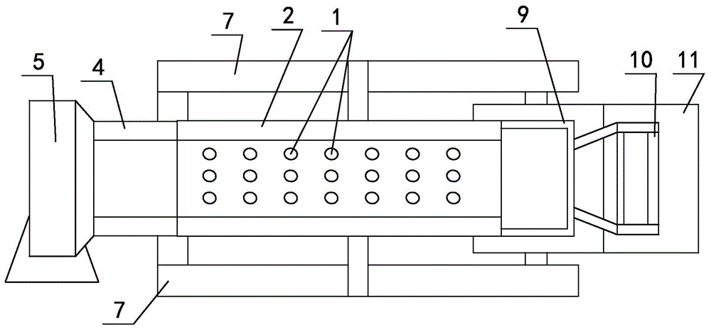
[0019] like figure 1 , figure 2 As shown, the soil quick separator for potato storage includes a bracket 7 with an L-shaped structure as a whole, and a chute 2 with a high left and a low right is inclined on the bracket 7, and the bottom of the chute 2 is provided with a number of The soil leakage hole 1 with a diameter of 20mm to 30mm is vertically installed on the left side wall of the bracket 7 with a lifting and conveying device 5. The outlet end of the top of the lifting and conveying device 5 is connected with a feeding chute 4 made of soft materials. The outlet is connected to the inlet at the upper left corner of the chute 2. Corresponding to the excavation direction of the soil leakage hole 1, a soil collection and treatment channel 6 is provided below the chute 2, and a bottom plate 11 is provided on the bracket 7 in the horizontal direction. The upper surface of the bottom plate 11 is divided into The upslope surface and the placement surface, the placement surfac...

Embodiment 2

[0023] On the basis of Example 1, the diameter of the soil leakage hole 1 was changed to 30mm; the vertical distance from the small fan 15 to the bottom of the chute 2 was changed to 400mm; the inclination angle of the chute 2 was changed to 40 degrees; The overall length of the chute 2 becomes 2500 mm. Others are the same as the first embodiment.

Embodiment 3

[0025] On the basis of Example 1, the diameter of the soil leakage hole 1 was changed to 25mm; the vertical distance from the small fan 15 to the bottom of the chute 2 was changed to 500mm; the inclination angle of the chute 2 was changed to 30 degrees; The overall length of the chute 2 becomes 2000 mm. Others are the same as the first embodiment.


PUM

PropertyMeasurementUnit
Lengthaaaaaaaaaa

Abstract

The invention relates to a machine enabling oil on potatoes to be quickly removed before potato storage, and belongs to the technical field of soil removal. The machine comprises a bracket which wholly adopts an L-shaped structure, wherein a chute which is high at a left part and low at a right part is obliquely formed in the bracket, and a plurality of soil leakage holes are formed in the bottom of the chute; a lifting conveying device is vertically mounted on the left side wall of the bracket; a soil collecting treatment passage is arranged under the chute; a bottom plate is arranged on the bracket in a horizontal direction, and the upper surface of the bottom plate is divided into an uphill slope surface and a placing surface; a potato collecting tank is formed in a blanking position at an outlet in the lower right corner of the chute; a fan mounting bracket is vertically arranged on the bracket in a horizontal direction, and a plurality of small-scale fans are mounted on the fan mounting bracket; the upper left end of the chute is hinged to the top of the bracket in a vertical direction through a pivot, a supporting leg is arranged at the bottom of the chute, springs are arranged between the supporting leg and the chute, and a vibrator is mounted at the bottom of the chute in the right side of the supporting leg. According to the machine disclosed by the invention, the length of the chute is effectively shortened, and the machine is quite convenient to carry.

Description

technical field [0001] The invention relates to a soil quick separator used before potatoes are stored, and belongs to the technical field of soil cleaning. Background technique [0002] At present, in the north, such as Gansu, the yield of potatoes is getting higher and higher, and the taste is also very good. One of the important reasons is that the soil here is sandy. With the growing area of ​​potatoes, the use of mechanized harvesting is one of the methods used, and its harvesting efficiency is very high, but when using mechanical equipment for harvesting, there is a lot of soil that cannot be cleaned up, and temporary storage is required. There will always be a lot of soil in the place, which will bring inconvenience to people. Now some mechanical equipment also has the function of soil cleaning, but because it was just unearthed at that time, the separation effect of soil and potatoes was still very poor. [0003] In the last month, the inventor designed a set of tec...

Claims


Application Information

Patent Timeline
IPC IPC(8): A23N12/02
Inventor 刘先华
Owner CHONGQING PINGMENG AGRI DEV
Why Eureka
Try Eureka