Superposition coding, decoding method, device, transmitter and receiver
A superposition coding and transmitter technology, applied in the field of communication, can solve the problem of low multi-user performance and achieve the effect of improving multi-user performance
- Summary
- Abstract
- Description
- Claims
- Application Information
AI Technical Summary
Problems solved by technology
Method used
Image

Examples
Embodiment 1
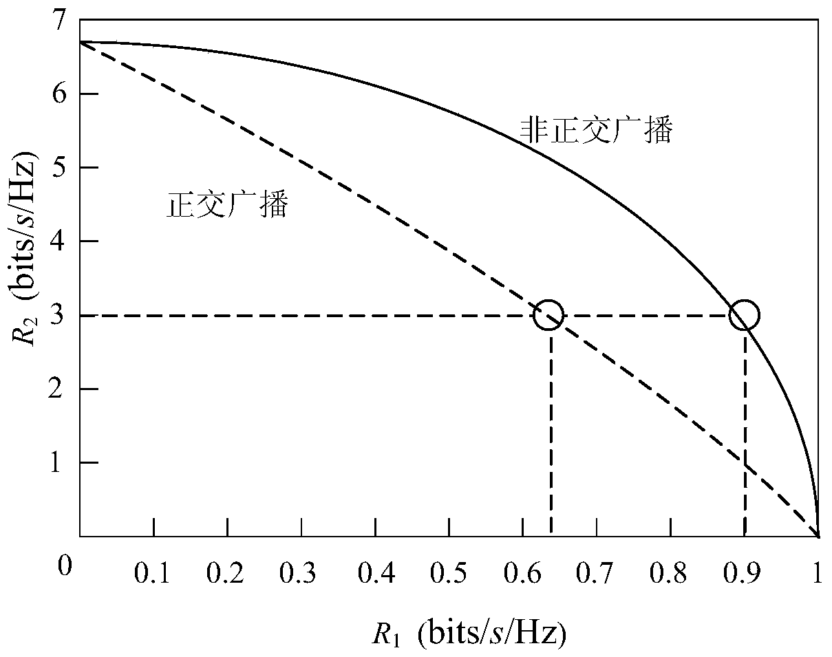
[0116] In order to emphasize the characteristics of the present invention, the following preferred typical embodiments are combined with simulation results to illustrate the obvious improvement in performance of the present invention.
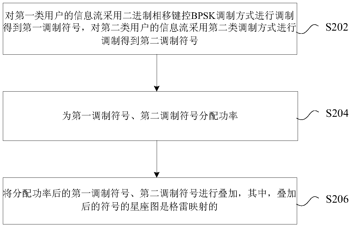
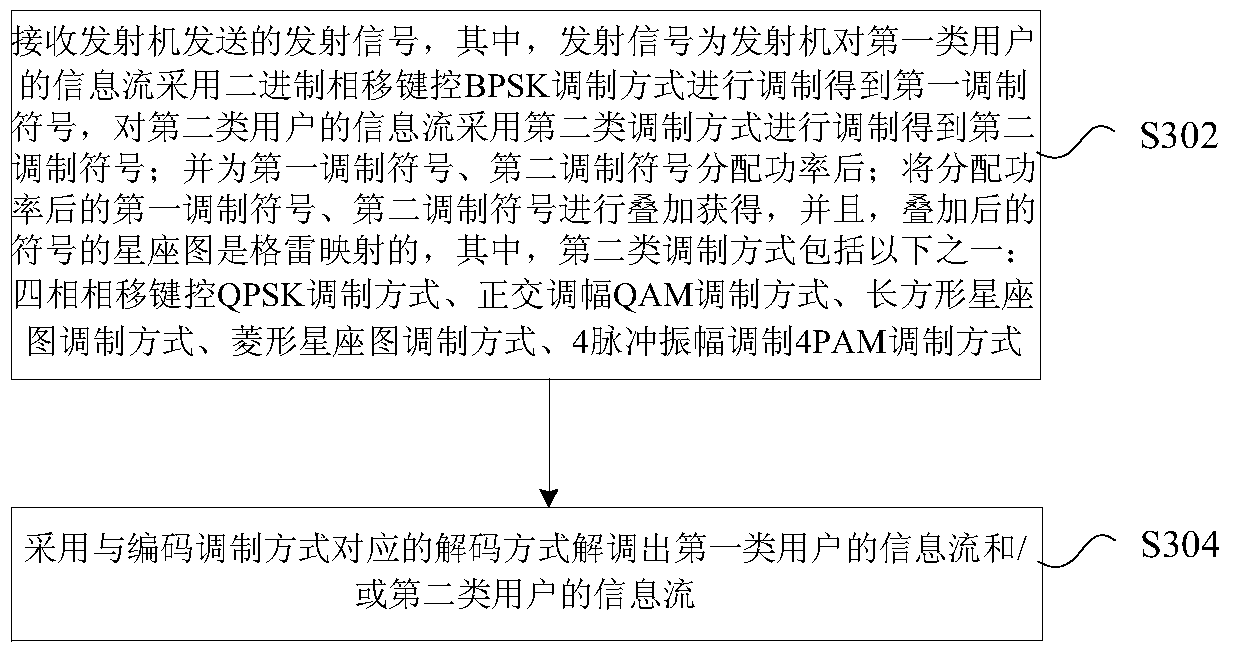
[0117] A downlink NOMA superposition coding scheme. The base station adopts the first type of BPSK modulation method to obtain the modulation symbol S1 for the edge user information, and allocates a certain power to S1. The first type of BPSK modulation means that the bit "0" is modulated into 1, and the bit "1" is modulated as -1; the central user information is modulated by QPSK to obtain the modulation symbol S2, and a certain power is allocated to S2. The base station mirrors the symbol S2 horizontally, and the mirrored symbol S can be expressed as Sign(x1)·x2+y2·i. The symbol S mirrored by S2 is directly superimposed on the symbol S1 to obtain the superimposed symbol S3. The superimposed constellation of symbol S3 is Gray mapped.
[0118...
example 2
[0124] In order to emphasize the characteristics of the present invention, the following typical embodiment 2 is preferred and combined with the simulation results to illustrate the obvious improvement in performance of the present invention.
[0125] A downlink NOMA superposition coding scheme. The base station uses the second type of BPSK modulation method to obtain the modulation symbol S1 for the edge user information, and allocates a certain power to S1. The second type of BPSK modulation means that the bit "0" is modulated into Modulates a bit "1" to The central user information is modulated by QPSK to obtain the modulation symbol S2, and a certain power is allocated to S2. The base station performs horizontal mirroring and 45-degree phase rotation on the symbol S2, and the symbol S after mirroring and 45-degree phase rotation can be expressed as e iπ / 4 ·(Sign(x1)·x2+y2·i). The symbol S after mirroring and 45-degree phase rotation is superimposed on the symbol S1 to ...
example 3
[0131] In order to emphasize the characteristics of the present invention, the following typical embodiment 3 is preferred and combined with the simulation results to illustrate the obvious improvement in performance of the present invention.
[0132] A downlink NOMA superposition coding scheme. The base station uses the first type of BPSK modulation method to obtain the modulation symbol S1 for the edge user information, and allocates a certain power to S1. The first type of BPSK modulation means that the bit "0" is modulated into 1, and the bit " 1" is modulated as -1; the central user information is modulated by 4-point PAM (4PAM modulation) to obtain the modulation symbol S2, and a certain power is allocated to S2. The symbol S1 and the symbol S2 are directly superimposed to obtain the superimposed symbol S3. The superimposed constellation of symbol S3 is Gray mapped.
[0133] Comparing the traditional superposition coding mode 1 in the first embodiment, according to the ...
PUM
 Abstract
Description
Claims
Application Information
 - R&D
- Intellectual Property
- Life Sciences
- Materials
- Tech Scout
- Unparalleled Data Quality
- Higher Quality Content
- 60% Fewer Hallucinations
Browse by: Latest US Patents, China's latest patents, Technical Efficacy Thesaurus, Application Domain, Technology Topic, Popular Technical Reports.
© 2025 PatSnap. All rights reserved.Legal|Privacy policy|Modern Slavery Act Transparency Statement|Sitemap|About US| Contact US: help@patsnap.com