Eureka AIR delivers breakthrough ideas for toughest innovation challenges, trusted by R&D personnel around the world.

Rotary transformer test clamping device

A resolver and clamping technology, which is applied in the direction of measuring devices, measuring device shells, instruments, etc., can solve problems such as inaccurate positioning, testing, and affecting product performance, and achieve rapid manufacturing and replacement and meet high-precision requirements. Effect

Active Publication Date: 2016-06-22
沈阳兴华航空电器有限责任公司
View PDF10 Cites 2 Cited by
  • Summary
  • Abstract
  • Description
  • Claims
  • Application Information

AI Technical Summary

Problems solved by technology

[0002] At present, due to the lack of clamping and micro-rotation equipment during the test of the resolver, the positioning index is inaccurate, and the electrical performance test cannot be carried out smoothly, which seriously affects the improvement and inspection of the product performance test.

Method used


Image

  • Rotary transformer test clamping device
  • Rotary transformer test clamping device
  • Rotary transformer test clamping device

Examples


Embodiment 1

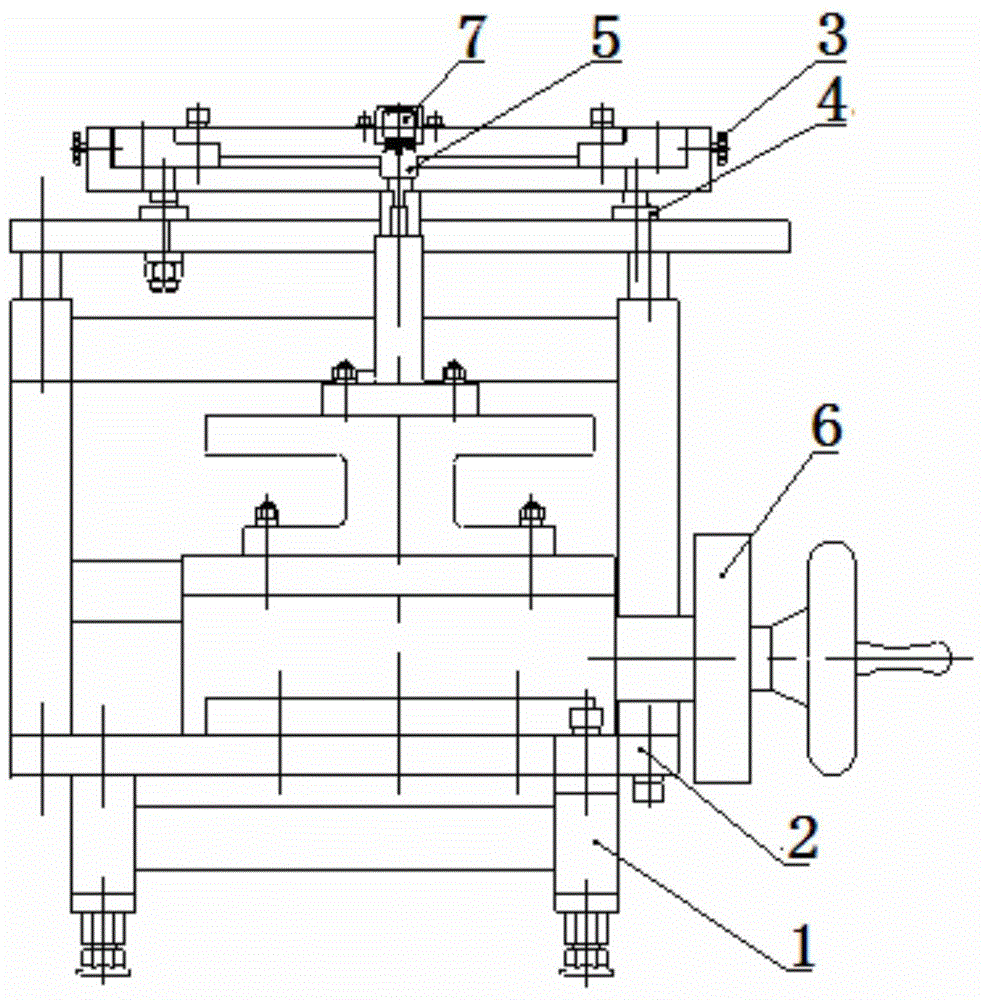
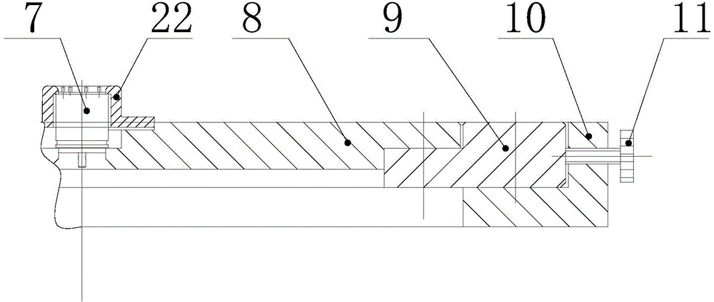
[0017] The resolver test and clamping equipment is composed as follows: a support 1, a base 2, a horizontal radial adjustment mechanism 3, a vertical axial adjustment mechanism 4, a rotor positioning mechanism 5, and a fine-tuning rotation mechanism 6; the base 2 is located on the support 1 Above, the base 2 is connected with the fine-tuning rotating mechanism 6, the rotor positioning mechanism 5 is connected with the fine-tuning rotating mechanism 6, the horizontal radial adjustment mechanism 3 is connected with the vertical axial adjustment mechanism 4 through the outer flange 10, and the vertical axial The adjustment mechanism 4 is connected with the support 1, and the casing of the resolver 7 is fixed on the positioning flange 8 through a gland and screws. The positioning flange 8, the middle flange 9, the outer flange 10 and the adjustment screw I11 form a horizontal radial adjustment mechanism 3; the positioning flange 8 is connected with the outer flange 10 through the m...


PUM


Abstract

Provided is a rotary transformer test clamping device. The rotary transformer test clamping device is composed of a support (1), a pedestal (2), a horizontal radial adjusting mechanism (3), a vertical axial adjusting mechanism (4), a rotor positioning mechanism (5) and a fine adjustment rotary mechanism (6). The pedestal (2) is fixed on the support (1). The rotor positioning mechanism (5) is connected with the fine adjustment rotary mechanism (6). The horizontal radial adjusting mechanism (3) is connected with the vertical axial adjusting mechanism (4). A shell body of a rotary transformer (7) is fixed on a positioning flange (8). The positioning flange (8), the intermediate flange (9), the outer flange (10) and an adjusting screw I (11) form the horizontal radial adjusting mechanism (3). The rotary transformer test clamping device has the advantages of accurate and simple clamping, convenient usage and reliable test data.

Description

technical field [0001] The invention relates to the technical field of structural design and application of testing equipment, and in particular provides a rotary transformer testing and clamping equipment. Background technique [0002] At present, when the resolver is tested, there is no clamping and micro-rotation equipment, which leads to inaccurate positioning and indexing, and the electrical performance test cannot be carried out smoothly, which seriously affects the improvement and inspection of product performance testing. [0003] People are eager to obtain a resolver test clamping device with excellent technical effect. Contents of the invention [0004] The purpose of the present invention is to provide a resolver test and clamping device with excellent technical effects, which can meet the high-precision requirements of resolver products on levelness and coaxiality, and realize the micro-rotation angle of the resolver rotor. To meet the design requirements and ...

Claims


Application Information

Patent Timeline
Patent Type & Authority Applications(China)
IPC IPC(8): G01R31/06G01R1/04
Inventor 刘晓杰
Owner 沈阳兴华航空电器有限责任公司
Why Eureka
Eureka Blog
Learn More