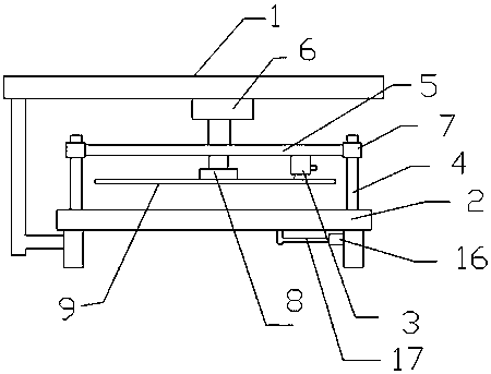
A fabric cutting machine
A cutting machine and cloth technology, which is applied in the cutting of textile materials, textiles and papermaking, etc., can solve the problems of not being able to cut multiple pieces of cloth at the same time, and the cutting efficiency is low, so as to improve the cutting efficiency, improve the cutting quality and ensure the cutting quality Effect
- Summary
- Abstract
- Description
- Claims
- Application Information
AI Technical Summary
Problems solved by technology
Method used
Image
Examples
Embodiment 1
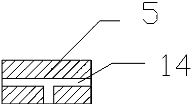
[0024] This embodiment includes a frame 1, a cutting table 2, a cutting machine 3, a guide post 4, a support rod 5, and a pressing cylinder 6. The cutting table 2 is fixedly installed on the frame 1, and the guide post 4 is fixed on the cutting machine. On the platform 2, the two ends of the support rod 5 are connected with a guide sleeve 7, the guide sleeve 7 is sleeved on the guide column 4, one end of the depressing cylinder 6 is connected to the support rod 5, and the other end is connected to the frame 1 Above, the cutting machine 3 is installed on the support rod 5, and the cutting machine 3 can slide on the support rod 5. It is characterized in that: the guide post 4 is provided with a connecting rod 8, and the connecting rod 8 is welded with a pressure plate 9. Pressing plate 9 is provided with cutting groove 10, and described cutting machine 3 comprises body 11 and circular blade 12, and circular blade 12 is fixed on the main body 11, and can rotate on main body 11, an...
Embodiment 2
[0030] This embodiment includes a frame 1, a cutting table 2, a cutting machine 3, a guide post 4, a support rod 5, and a pressing cylinder 6. The cutting table 2 is fixedly installed on the frame 1, and the guide post 4 is fixed on the cutting machine. On the platform 2, the two ends of the support rod 5 are connected with a guide sleeve 7, the guide sleeve 7 is sleeved on the guide column 4, one end of the depressing cylinder 6 is connected to the support rod 5, and the other end is connected to the frame 1 Above, the cutting machine 3 is installed on the support rod 5, and the cutting machine 3 can slide on the support rod 5. It is characterized in that: the guide post 4 is provided with a connecting rod 8, and the connecting rod 8 is welded with a pressure plate 9. Pressing plate 9 is provided with cutting groove 10, and described cutting machine 3 comprises body 11 and circular blade 12, and circular blade 12 is fixed on the main body 11, and can rotate on main body 11, an...
Embodiment 3
[0032]This embodiment includes a frame 1, a cutting table 2, a cutting machine 3, a guide post 4, a support rod 5, and a pressing cylinder 6. The cutting table 2 is fixedly installed on the frame 1, and the guide post 4 is fixed on the cutting machine. On the platform 2, the two ends of the support rod 5 are connected with a guide sleeve 7, the guide sleeve 7 is sleeved on the guide column 4, one end of the depressing cylinder 6 is connected to the support rod 5, and the other end is connected to the frame 1 Above, the cutting machine 3 is installed on the support rod 5, and the cutting machine 3 can slide on the support rod 5. It is characterized in that: the guide post 4 is provided with a connecting rod 8, and the connecting rod 8 is welded with a pressure plate 9. Pressing plate 9 is provided with cutting groove 10, and described cutting machine 3 comprises body 11 and circular blade 12, and circular blade 12 is fixed on the main body 11, and can rotate on main body 11, and...
PUM
 Abstract
Description
Claims
Application Information
 - Generate Ideas
- Intellectual Property
- Life Sciences
- Materials
- Tech Scout
- Unparalleled Data Quality
- Higher Quality Content
- 60% Fewer Hallucinations
Browse by: Latest US Patents, China's latest patents, Technical Efficacy Thesaurus, Application Domain, Technology Topic, Popular Technical Reports.
© 2025 PatSnap. All rights reserved.Legal|Privacy policy|Modern Slavery Act Transparency Statement|Sitemap|About US| Contact US: help@patsnap.com


