Marking positioning device

A technology of positioning device and ejecting device, applied in the direction of printing device, printing, etc., can solve the problems of unclear marking on the surface of the rotor, inconvenient positioning of the rotor positioning device, etc., and achieve the effect of stable positioning and clear marking

Inactive Publication Date: 2016-06-22
WUXI FORMEN TECHN
View PDF0 Cites 1 Cited by
  • Summary
  • Abstract
  • Description
  • Claims
  • Application Information

AI Technical Summary

Problems solved by technology

[0002] The rotating body supported by the bearing is called the rotor. The rotor is mostly the main rotating part in the power machinery and working machinery. The marking operation is required in the rotor processing engineering. The marking operation is performed by the marking machine after positioning by the positioning device. The positioning of the rotor positioning device is inconvenient, and the marking on the rotor surface is not clear when marking on the line

Method used


Image

  • Marking positioning device
  • Marking positioning device

Examples


Embodiment Construction

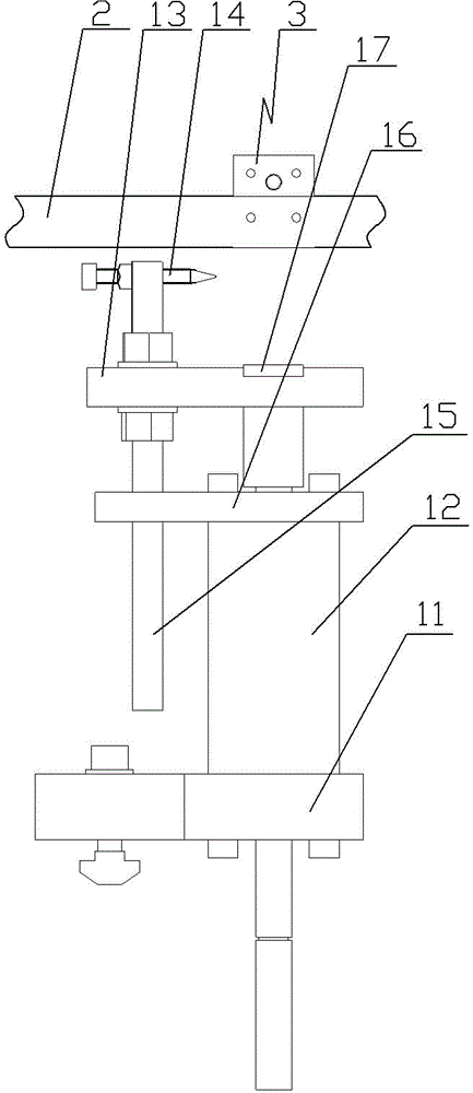
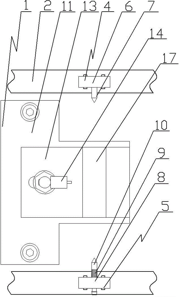
[0010] See figure 1 , figure 2 As shown, a marking positioning device includes a lower ejecting device 1 and a side clamp 3 installed on a conveyor belt 2. The side clamp 3 includes a fixed clamp 4 and a movable clamp 5 that cooperate with each other. The fixed clamp 4 includes a fixed Installed on the fixed fixture bottom plate 6 of the conveyor belt 2, the fixed top cone 7 is fixedly installed on the fixed fixture bottom plate 6, the movable fixture 5 includes a movable fixture bottom plate 8 fixedly installed on the conveyor belt 2, and the movable fixture bottom plate 8 is installed through a compression spring 9. The top cone 10, the lower jacking device 1 is arranged at the lower end of the side fixture 3, the lower jacking device 1 includes a jacking cylinder fixing plate 11, and the jacking cylinder 12 is fixedly installed on the jacking cylinder fixing plate 11, and the piston of the jacking cylinder 12 Install the driving rod fixing seat 13 on the rod, and the work...


PUM


Abstract

The invention relates to the rotor processing technology field, particularly relates to a marking positioning device, can realize stable positioning of a rotor and guarantees intelligible marking. The device comprises a lower portion ejection device and a side portion clamp mounted on a conveying belt, wherein the side portion clamp comprises a fixed clamp and a movable clamp which are in mutual matching with each other, the fixed clamp comprises a fixed clamp bottom board fixedly mounted on the conveying belt, the fixed clamp bottom board is fixedly equipped with a fixing top cone, the movable clamp comprises a movable clamp bottom board fixedly mounted on the conveying belt, the movable clamp bottom board is equipped with a movable top cone through a pressure spring, the lower portion ejection device is arranged at the lower end of the side portion clamp, the lower portion ejection device comprises an ejection cylinder fixing board, the ejection cylinder fixing board is fixedly equipped with an ejection cylinder, a piston rod of the ejection cylinder is equipped with a driving lever fixing seat, and one end of the driving lever fixing seat is equipped with a workpiece pull pin.

Description

technical field [0001] The invention relates to the technical field of rotor processing, in particular to a marking and positioning device. Background technique [0002] The rotating body supported by the bearing is called the rotor. The rotor is mostly the main rotating part in the power machinery and working machinery. The marking operation is required in the rotor processing engineering. The marking operation is performed by the marking machine after positioning by the positioning device. The positioning of the rotor positioning device is inconvenient, and the marking on the rotor surface is not clear when marking on the line. Contents of the invention [0003] In order to solve the above problems, the present invention provides a marking positioning device, which can realize stable positioning of the rotor and ensure clear marking. [0004] Its technical solution is as follows: a marking positioning device, which is characterized in that it includes a lower lifting de...

Claims


Application Information

Patent Timeline
Patent Type & Authority Applications(China)
IPC IPC(8): B41J11/00
Inventor 田芸
Owner WUXI FORMEN TECHN
Why Eureka
Try Eureka