
Flat vibration motor

A flat vibration motor and cover plate technology, applied in electric components, control mechanical energy, electrical components, etc., can solve the problems of uneven product quality, high assembly difficulty, and difficulty in ensuring accuracy.

Inactive Publication Date: 2016-06-15
KUNSHAN LIANTAO ELECTRONICS CO LTD
View PDF4 Cites 2 Cited by
  • Summary
  • Abstract
  • Description
  • Claims
  • Application Information

AI Technical Summary

Problems solved by technology

Existing flat vibrating flat motors generally contain a large number of parts, with complex structure and assembly, high difficulty in assembly, and difficulty in ensuring accuracy, resulting in uneven product quality

Method used


Image

  • Flat vibration motor
  • Flat vibration motor
  • Flat vibration motor

Examples


Embodiment Construction

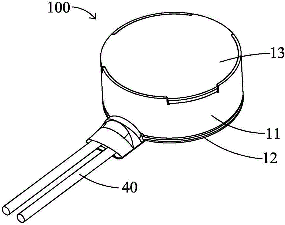
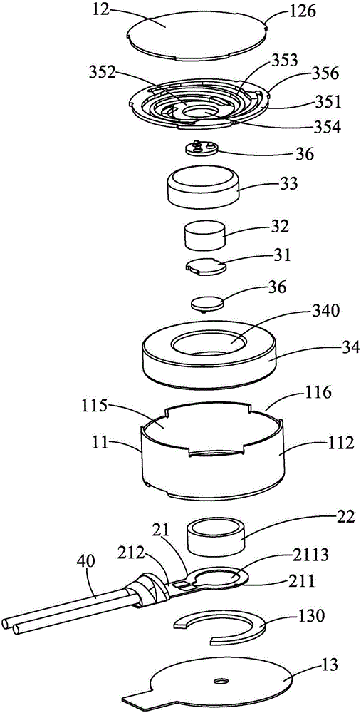
[0010] see Figure 1 to Figure 4 As shown, the flat vibration motor 100 of the present invention includes a casing 11, an upper cover plate 12, a lower cover plate 13, a circuit board 21, a coil 22, a pole core 31, a magnetic steel 32, a magnetic bowl 33, a mass block 34, and a spring plate 35 , two buffer spacers 36.

[0011] The casing 11 includes a bottom wall 111, an annular side wall 112 protruding upward from the periphery of the top wall 111, and a receiving space 115 formed between the bottom wall 111 and the side wall 112. The bottom wall 111 is provided with a vertically penetrating A circular receiving hole 113 and an outlet 114 , the receiving hole 113 is disposed at the center of the bottom wall 111 , and the outlet 114 penetrates the bottom wall 111 from the receiving hole 113 to the outside. The top of the sidewall 112 defines a plurality of notches 116 at intervals.

[0012] The upper cover 12 is downwardly fixed on the side wall 112 to cover the receiving sp...


PUM


Abstract

The invention relates to a flat vibration motor, which comprises a housing, an upper cover plate, a lower cover plate, a circuit board, a coil, a pole core, a magnetic steel, a magnetic bowl, a mass block and a spring board, wherein the magnetic steel is fixed in the magnetic bowl; the mass block is provided with a fixing hole for fixing the magnetic bowl; the spring board comprises an outer ring, an inner ring and a plurality of elastic connection parts connecting the inner ring and the outer ring; the outer ring is fixed on the housing; the top surface of the magnetic bowl or the mass block is fixed in the inner ring; the housing is provided with a bottom wall, an annular side wall extending upwardly and convexly from the periphery of the bottom wall and accommodating space formed between the bottom wall and the side wall; a vertical-through accommodating hole is arranged in the bottom wall; the circuit board, the coil and the lower cover plate form a stator module and are together upwardly assembled in the housing. Thus, the assembly precision is improved.

Description

technical field [0001] The invention relates to a flat vibration motor. Background technique [0002] Flat vibration motors are widely used in mobile phones, tablet computers or environments that require vibration to realize the vibration function, instead of sound to remind users, and avoid disturbing others or generating noise. Existing flat vibrating flat motors generally contain a large number of parts, have complex structure and assembly, are difficult to assemble, and difficult to guarantee precision, resulting in uneven product quality. Contents of the invention [0003] An object of the present invention is to provide a flat vibration motor with improved assembly accuracy. [0004] In order to achieve the aforementioned purpose, the present invention adopts the following technical solutions: a flat vibrating motor, which includes a casing, an upper cover, a lower cover, a circuit board, a coil, a pole core, a magnetic steel, a magnetic Bowl, a mass block and a sp...

Claims


Application Information

Patent Timeline
Patent Type & Authority Applications(China)
IPC IPC(8): H02K33/02H02K7/075
CPCH02K33/02H02K7/075
Inventor 李伟
Owner KUNSHAN LIANTAO ELECTRONICS CO LTD
Learn More