
Carbon composite material, preparation method for carbon composite material and battery

A technology of carbon composite materials and silicon-based materials, applied in battery electrodes, secondary batteries, circuits, etc., can solve problems such as poor cycle performance

Active Publication Date: 2016-06-15
SUZHOU GCLSI SCI & TECH IND APPL RES INST CO LTD +3
View PDF5 Cites 15 Cited by
  • Summary
  • Abstract
  • Description
  • Claims
  • Application Information

AI Technical Summary

Problems solved by technology

[0006] Based on this, it is necessary to provide a carbon composite material with high cycle performance to solve the problem of poor cycle performance of existing composite materials

Method used


Image

  • Carbon composite material, preparation method for carbon composite material and battery
  • Carbon composite material, preparation method for carbon composite material and battery
  • Carbon composite material, preparation method for carbon composite material and battery

Examples


preparation example Construction

[0042] A method for preparing a carbon composite material, comprising the steps of:

[0043] S1. Coating a silicon-based material or a tin-based material on graphite particles to obtain a first core-shell material;

[0044] S2. Uniformly disperse the first core-shell material and the carbon precursor in the dispersant, and react at a temperature of 160-180° C. and a pressure of 0.15-0.3 MPa for 3-6 hours to obtain a carbon composite material.

[0045] In S1, the coating can choose chemical coating or physical coating according to the actual situation. Among them, chemical coating can adopt vapor phase deposition method, such as SiO 2 As the raw material, a low-vacuum tube furnace system is used, and Ar gas or N 2 Gas is used as the carrier gas, the reaction pressure is adjusted to 50000Pa, the temperature is 900-1200°C, and the reaction is carried out for 1-3h. Wherein, the physical coating may be ball mill coating or stirring coating, for example, the nano silicon fiber an...

Embodiment 1

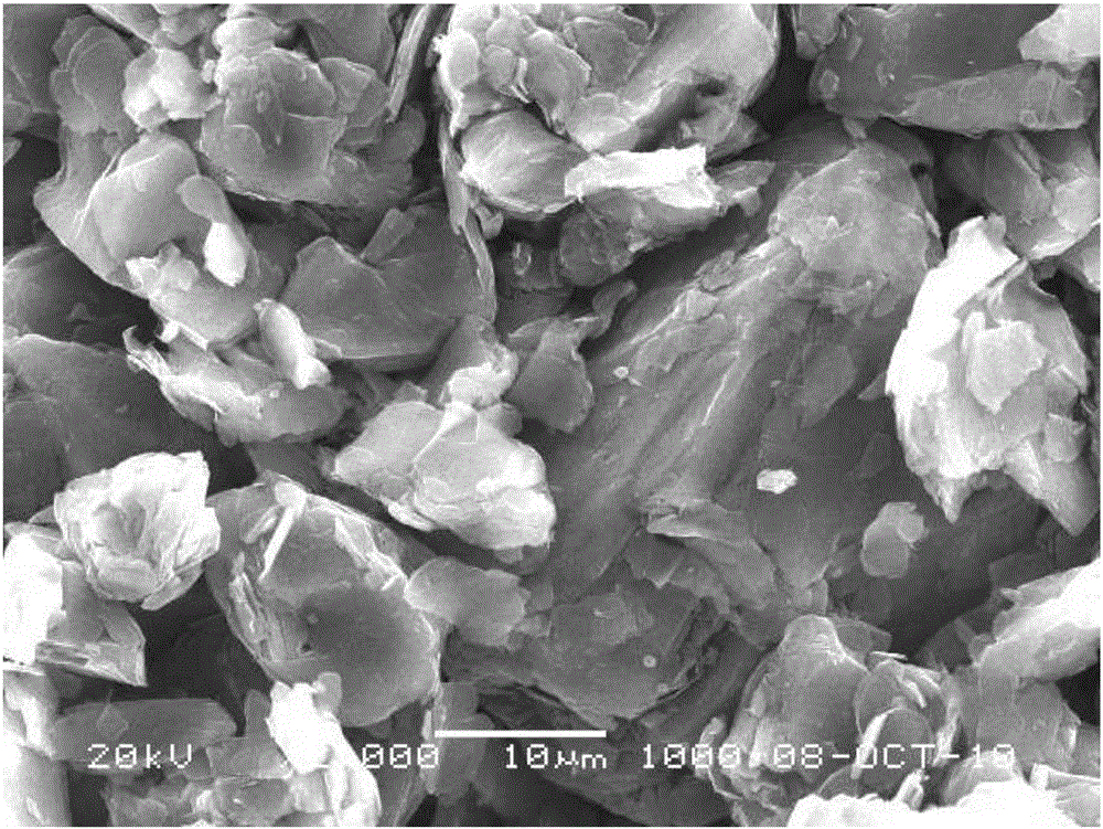
[0055] 30g of natural graphite (average particle size: 25μm) was placed in a ball mill, and then 3g of nano silicon fibers (diameter less than 100nm, length 1μm-50μm) were added to obtain the first core-shell material.

[0056] The obtained first core-shell material was placed in a 1L tempered reaction kettle, and then 200g of cellulose aqueous solution (1wt%) was added; the reaction was carried out at 170°C and 0.25MPa for 6h.

[0057] The obtained carbon composite material is denoted as A1.

Embodiment 2

[0059] In a low-vacuum tube furnace system, 6 g of SiO 2 As a raw material, use Ar gas as a carrier gas, react at a pressure of 50,000 Pa and a temperature of 1,000°C for 2 hours, and wait for the first core-shell material.

[0060] The obtained first core-shell material was placed in a 1L tempered reaction kettle, and then 300g of sucrose aqueous solution (1wt%) was added; the reaction was carried out at 180°C and 0.15MPa for 5h.

[0061] The obtained carbon composite material is denoted as A2.


PUM

PropertyMeasurementUnit
particle sizeaaaaaaaaaa
thicknessaaaaaaaaaa
thicknessaaaaaaaaaa

Abstract

The invention relates to the field of batteries, in particular to a carbon composite material. The carbon composite material comprises a core, a middle layer covering the core, and an outer layer covering the middle layer, wherein the core is graphite; the middle layer is a silicon-based material or a tin-based material; and the outer layer is porous carbon. According to the carbon composite material, the silicon-based material or the tin-based material is positioned between the graphite and the porous carbon, so that the material pulverization can be inhibited; the porous carbon reserves sufficient space, so that the cyclic stress generated by expansion of the silicon-based material or the tin-based material can be buffered and the pulverization is avoided; and therefore, the carbon composite material has good cyclic performance. In addition, the porous carbon of the outer layer can effectively prevent the silicon-based material or the tin-based material from being in direct contact with an electrolyte solution, reduce the irreversible capacity and improve the conductive performance of the carbon composite material; and the porous carbon is favorable for insertion and extraction of lithium ions due to porosity. The invention furthermore discloses a preparation method for the carbon composite material and a battery.

Description

technical field [0001] The invention relates to the field of batteries, in particular to a carbon composite material, a preparation method thereof and a battery. Background technique [0002] Compared with traditional graphite anode materials, silicon has an ultra-high theoretical specific capacity (4200mAh / g) and a lower delithiation potential (<0.5V), and the voltage platform of silicon is slightly higher than that of graphite, which is not easy to charge when charging. The behavior of lithium precipitation on the surface occurs, and the safety performance is better, so it has become a new research direction for the negative electrode material of the battery. [0003] However, since silicon is a semiconductor material, when it is used as a battery negative electrode material, its own conductivity is low, and the insertion and extraction of lithium ions in the process of charging and discharging will cause the volume of silicon to expand and shrink by more than 300%, whi...

Claims


Application Information

Patent Timeline
Patent Type & Authority Applications(China)
IPC IPC(8): H01M4/36H01M4/38H01M4/587H01M4/62H01M10/0525
CPCH01M4/366H01M4/386H01M4/387H01M4/587H01M4/625H01M4/628H01M10/0525Y02E60/10
Inventor 相江峰郝三存
Owner SUZHOU GCLSI SCI & TECH IND APPL RES INST CO LTD
Learn More