A transformer coil annular axial compression device and compression method

A technology of transformer coil and compression device, which is applied in inductance/transformer/magnet manufacturing, coil manufacturing, electrical components, etc., to achieve the effect of ensuring compactness, high use efficiency and improving product quality

Active Publication Date: 2018-05-11
TBEA SHENYANG TRANSFORMER GRP CO LTD
View PDF4 Cites 0 Cited by
  • Summary
  • Abstract
  • Description
  • Claims
  • Application Information

AI Technical Summary

Problems solved by technology

[0004] At present, the annular axial compression device of the transformer coil that can meet the above requirements has not been reported yet.

Method used


Image

  • A transformer coil annular axial compression device and compression method
  • A transformer coil annular axial compression device and compression method
  • A transformer coil annular axial compression device and compression method

Examples


Embodiment Construction

[0029] The present invention will be further elaborated below in conjunction with the accompanying drawings of the description.

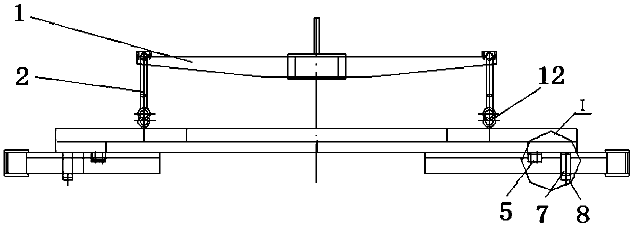
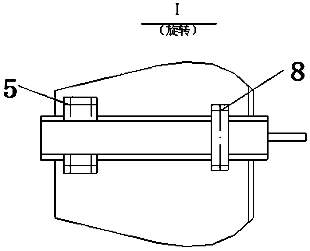
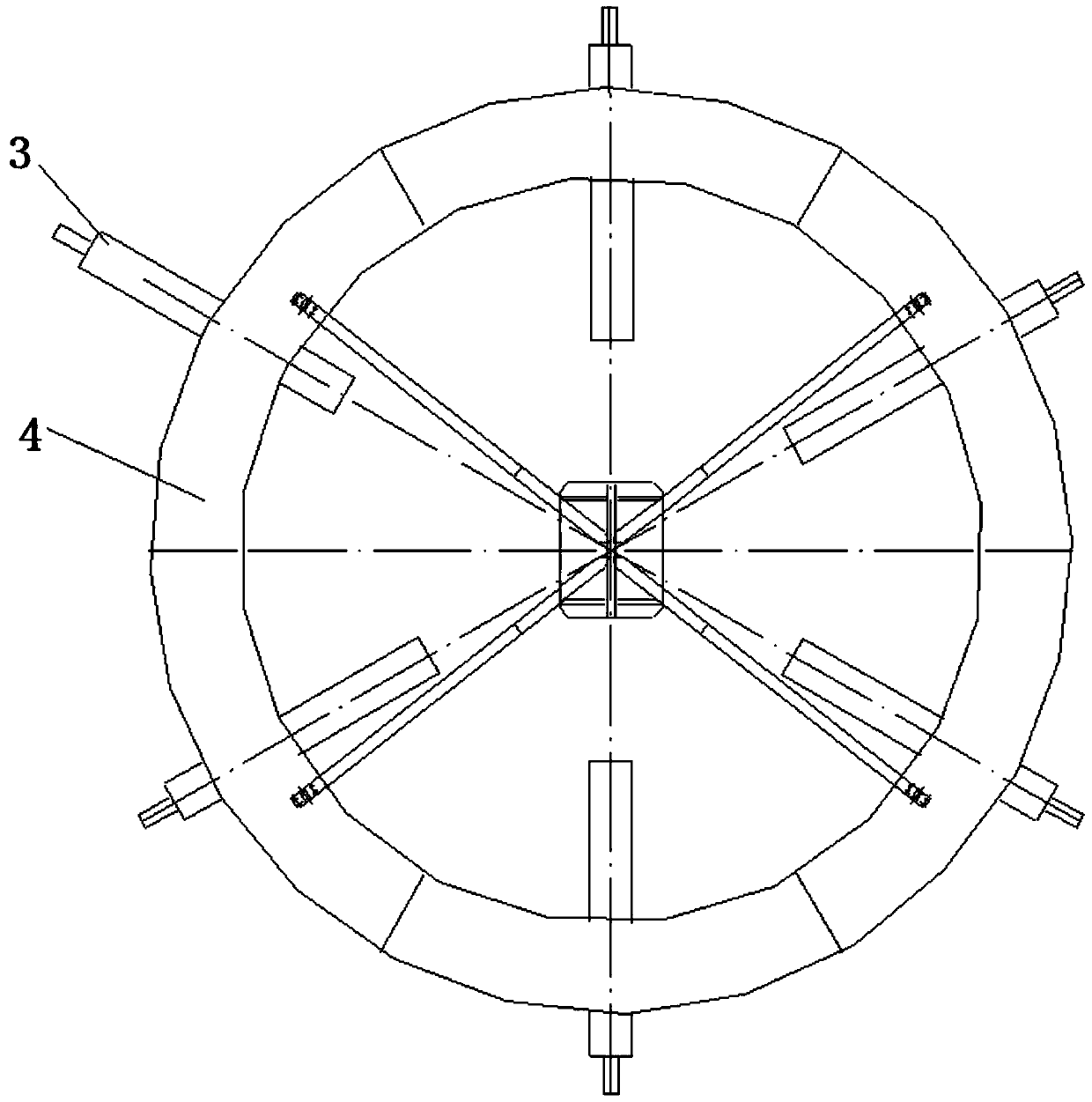
[0030] like Figure 1A ~ 1C As shown, a transformer coil annular axial compression device of the present invention is characterized in that it has a pressure plate 4 and an upper hanging plate 1, the two are connected by a chain 2, and the lower part of the pressure plate 4 is provided with multiple Adjust the pressure beam 3 of the position. The part of the lower part of the pressure plate 4 corresponding to the pressure beam 3 is provided with a pull-out structure. The pull-out structure includes a slide rail 5 and ferrules. The slide rail and ferrule are fixedly installed on the bottom surface of the pressure plate 4 along the radial direction of the pressure plate 4. 3 sides are slidably connected to the slide rail 5, and the pressure beam 3 is inserted into the ferrule.

[0031] like Figure 1C As shown, the ferrule includes two connecting p...


PUM


Abstract

The invention relates to a ring-shaped axial compression device and a compression method for a transformer coil. It has a pressure plate and an upper hanging plate, the two are connected by a chain, and the lower part of the pressure plate is provided with a plurality of pressure beams whose positions can be adjusted along the radial direction of the pressure plate; The method includes the following steps: adjusting a plurality of adjustable pressure beams of the annular axial compression device according to the inner diameter of the coil to be preloaded; hoisting the annular axial compression device by a crane, and directly placing it on the coil segment to be preloaded; Control the preloading time for 10 to 20 minutes; after the preloading of the coil line segment is completed, lift and remove the annular axial compression device, and the preloading process ends once. The invention solves the problem of pre-pressing during the winding process of the coil and before demoulding after the winding is completed, thereby solving the problem that the winding of the coil with a large wire gauge or a special structure is not tightly wound.

Description

technical field [0001] The invention relates to a tool for manufacturing a transformer, in particular to a ring-shaped axial compression device and a compression method for a transformer coil. Background technique [0002] The transformer industry is developing rapidly, and user units have higher and higher requirements for the performance of transformer products. Therefore, according to the needs of users, we continue to develop innovative high-voltage, high-current large-capacity transformers and converter transformers. These transformers are also major products in national key projects. The coil wire structure of these products is complex, and it is difficult to ensure the axial tightness of the coil during the winding process. Especially when using a vertical winding machine, the axial tightness is the key control measure to avoid the wire segment from falling down and avoiding the short circuit of the wire segment. [0003] In view of the above reasons, it is necessary...

Claims


Application Information

Patent Timeline
Patent Type & Authority Patents(China)
IPC IPC(8): H01F41/066H01F41/04
Inventor 张冬梅李阳阳
Owner TBEA SHENYANG TRANSFORMER GRP CO LTD
Why Eureka
Try Eureka