Measuring method of two-dimensional spacecraft angular rate based on gyro flywheel system
A technology of gyro flywheel and measurement method, applied in the field of inertial navigation, achieves high angular rate measurement accuracy and avoids the effect of dynamic calibration
- Summary
- Abstract
- Description
- Claims
- Application Information
AI Technical Summary
Problems solved by technology
Method used
Image
Examples
specific Embodiment approach 1
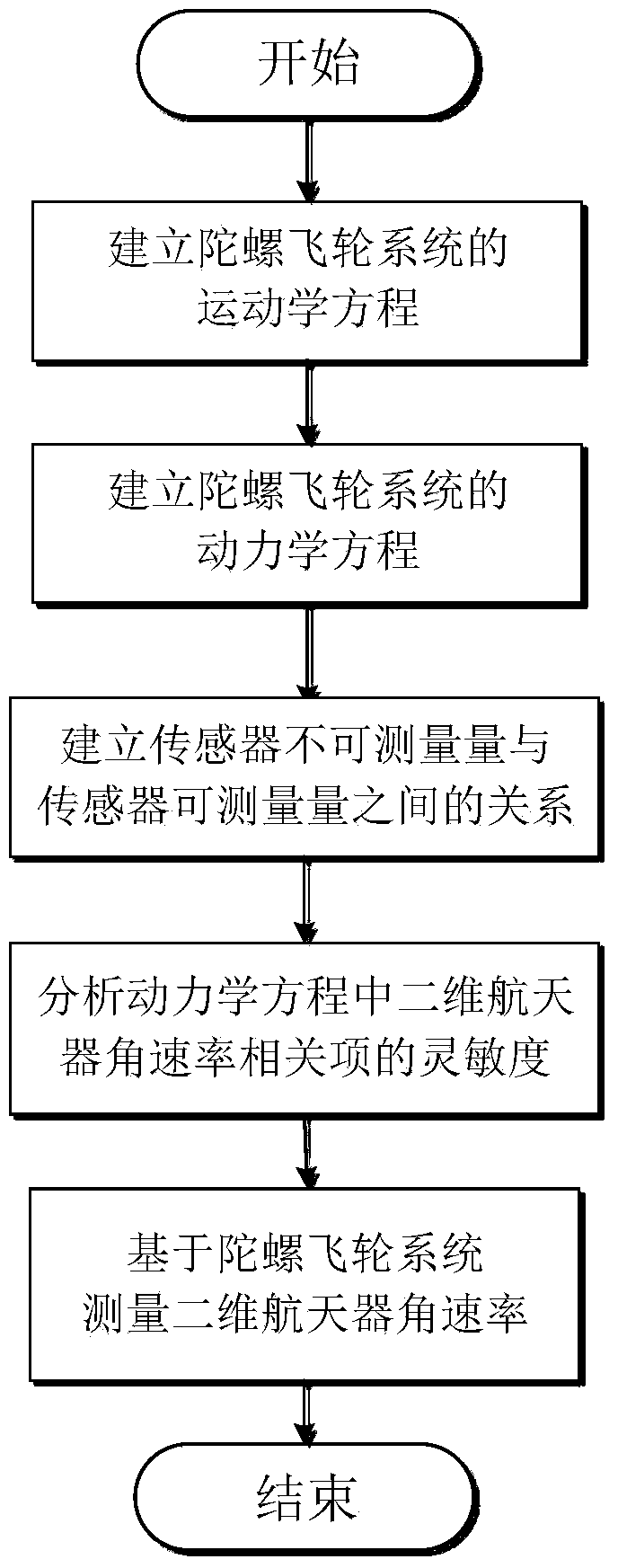
[0022] Specific implementation mode one: the method for measuring the angular rate of the two-dimensional spacecraft based on the gyro flywheel system in this implementation mode is implemented according to the following steps:
[0023] Step 1, establishing the kinematic equation of the gyro flywheel system;
[0024] Step 2, establishing the dynamic equation of the gyro flywheel system;
[0025] Step 3, establishing the relationship between the unmeasurable quantity of the sensor and the measurable quantity of the sensor;
[0026] Step 4, analyzing the sensitivity of the two-dimensional spacecraft angular rate related items in the dynamic equation;
[0027] Step 5. Measure the angular rate of the two-dimensional spacecraft based on the gyro flywheel system.
specific Embodiment approach 2
[0028] Specific embodiment two: this embodiment is different from specific embodiment one: it is characterized in that, described step one establishes the kinematic equation of gyro flywheel system and realizes according to the following steps:
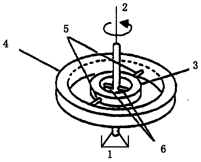
[0029] Such as figure 2 As shown, the core components of the gyro flywheel system are composed of a housing 1, a motor shaft 2, a balance ring 3, a rotor 4, an outer flexible shaft 5, and an inner flexible shaft 6, wherein the motor shaft 2 is connected to a pair of inner flexible shafts 6 and The inner side of the gimbal 3 is connected, the outer side of the gimbal 3 is connected to the inner side of the rotor 4 through a pair of outer flexible shafts 5, and the inner flexible shaft 6 is kept orthogonal to the outer flexible shaft 5; , and the body coordinate system of the rotor are respectively Ox c the y c z c , Ox m the y m z m , Ox g the y g z g , Ox r the y r z r , the relative angular position relationship among bo...
specific Embodiment approach 3
[0041] Specific embodiment three: this embodiment is different from specific embodiment one or two: it is characterized in that, described step 2 establishes the dynamic equation of gyroscope flywheel system and realizes according to the following steps:
[0042] Step 21, constructing the energy equation of the gyro flywheel system;
[0043] The kinetic energy T of the gyro flywheel system is composed of three parts: the motor shaft, the balance ring and the rotor. For example, the generalized velocity quadratic form of the kinetic energy T in formula (4) is expressed as:
[0044]
[0045] Among them, I mi , I gi , I ri Respectively expressed as the moment of inertia of the motor shaft, balance ring and rotor on the inertial spindle, i=x, y, z;
[0046] The potential energy V of the gyro flywheel system is caused by the elastic deformation of the inner and outer flexible axes of the gyro flywheel system, as shown in formula (5):
[0047]
[0048] Among them, K x ,K ...
PUM
 Abstract
Description
Claims
Application Information
 - Generate Ideas
- Intellectual Property
- Life Sciences
- Materials
- Tech Scout
- Unparalleled Data Quality
- Higher Quality Content
- 60% Fewer Hallucinations
Browse by: Latest US Patents, China's latest patents, Technical Efficacy Thesaurus, Application Domain, Technology Topic, Popular Technical Reports.
© 2025 PatSnap. All rights reserved.Legal|Privacy policy|Modern Slavery Act Transparency Statement|Sitemap|About US| Contact US: help@patsnap.com


