Gas flow adjusting valve

A gas flow and valve adjustment technology, which is applied in the direction of sliding valves, valve details, valve devices, etc., can solve problems such as insufficient nozzle flow stability, gas flow adjustment lag, and gas flow changes, etc., to prolong service life and ensure stable performance , Enhance the effect of sealing performance

Active Publication Date: 2016-06-15
四川省诚德蓝天环保科技有限公司
View PDF9 Cites 0 Cited by
  • Summary
  • Abstract
  • Description
  • Claims
  • Application Information

AI Technical Summary

Problems solved by technology

However, the structure of the injection rail spool in the prior art is complicated, the stability of the nozzle flow is insufficient, and the adjustment of the gas flow is relatively lagging in the adjustment process, such as the gas ejected by the nozzle when increasing or decreasing the flow output. Flow changes slowly

Method used


Image

  • Gas flow adjusting valve
  • Gas flow adjusting valve

Examples


Embodiment 1

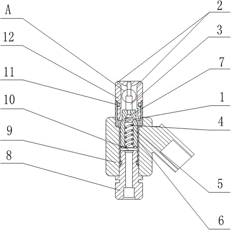
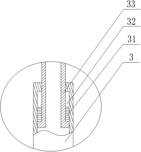
[0022] like figure 1 and figure 2 As shown, the present embodiment includes an electromagnetic valve seat 9 provided with an electromagnetic coil on the inner wall, and a movable valve body 5 and a housing 6 are sequentially arranged in the electromagnetic valve seat 9 from the inside to the outside, and the upper end of the housing 6 faces outward. Extended, and the lower end of the housing 6 is provided with an internal hollow connecting piece 8, there is a gap between the upper end of the connecting piece 8 and the lower end of the movable valve body 5, and the valve nozzle 12 is screwed on the extension end of the housing 6, so The inside of the movable valve body 5 has an air passage 7 communicating with the middle part of the connecting piece 8, the spring 4 is arranged in the air passage 7, and two passages communicating with the air passage 7 are opened on the side wall of the movable valve body 5. The hole 1, the upper end of the movable valve body 5 communicates wi...


PUM


Abstract

The invention discloses a gas flow adjusting valve. The gas flow adjusting valve comprises an electromagnetic valve seat. A movable valve body and a shell are sequentially arranged in the electromagnetic valve seat from interior to exterior. The upper end of the shell extends outwards, and a hollow connecting piece is arranged at the lower end of the shell. A gap is reserved between the upper end of the connecting piece and the lower end of the movable valve body. The extending end of the shell is in threaded connection with a valve nozzle. An air flue communicating with the middle portion of the connecting piece is formed in the movable valve body. A spring is arranged in the air flue. Two through holes communicating with the air flue are formed in the side wall of the movable valve body. The upper end of the movable valve body communicates with the interior of the valve nozzle. A plurality of blow holes are formed in the circumference of the top end of the valve nozzle. The multiple blow holes are formed in the outer circumference of the top of the valve nozzle to adapt to stable gas output when the amount of gas in the air flue is increased or decreased, the valve nozzle is in threaded connection with the extending end of the shell so that the valve nozzle can be rapidly replaced when damaged, overall replacement of a valve element, the electromagnetic valve seat and other components is avoided, and the using cost is reduced.

Description

technical field [0001] The invention relates to a gas injection rail, in particular to a gas flow regulating valve. Background technique [0002] With the rapid growth of car ownership, the problems of environmental pollution and shortage of oil resources are becoming more and more serious. To this end, countries around the world are actively developing new energy vehicles. Among them, natural gas vehicles are being popularized and promoted around the world due to their three major characteristics: low emissions, suppression of greenhouse effect, and independence from oil. In our country, many urban buses and taxis have a large number of fuel vehicles that have switched or are switching to compressed natural gas (CNG) or liquefied petroleum gas (LPG). With the rapid increase in the number of gas vehicles in my country, it is imperative to develop gas heaters that match it. [0003] In the electronic control injection system of the gas fuel engine, one of the most critical...

Claims


Application Information

Patent Timeline
IPC IPC(8): F02M21/02F16K3/24F16K31/06
CPCF02M21/0239F02M21/0257F16K3/24F16K31/0668Y02T10/30
Inventor 谢成忠
Owner 四川省诚德蓝天环保科技有限公司
Why Eureka
Try Eureka