A cycle feeding mechanism of a printing machine

A technology of feeding mechanism and printing machine, applied in thin material handling, transportation and packaging, object supply and other directions, can solve the problems of high production cost, increase the cost of enterprise land and workshop, and large floor space, so as to reduce the waiting time of workers, The effect of reducing the floor space and saving land costs

Active Publication Date: 2018-04-24
TAOTECH DIGITAL TECH
View PDF6 Cites 1 Cited by
  • Summary
  • Abstract
  • Description
  • Claims
  • Application Information

AI Technical Summary

Problems solved by technology

[0002] The feeding mechanism of the current printing machine adopts a separate feeding method, that is, the material is loaded at the printing station, and the material is taken out at the printing station after the printing is completed. Therefore, during the printing process of the printing medium, the worker can only wait at the printing station. The production efficiency of this printing method is very low, the automation level is low, and the production cost is high.
In addition, the traditional printing equipment is bulky, especially when it involves multiple stations, and the printing equipment is very long. Therefore, it occupies a very large area and increases the cost of land and factory buildings for enterprises.

Method used


Image

  • A cycle feeding mechanism of a printing machine
  • A cycle feeding mechanism of a printing machine
  • A cycle feeding mechanism of a printing machine

Examples


Embodiment Construction

[0026] The present invention will be further described below in conjunction with accompanying drawing:

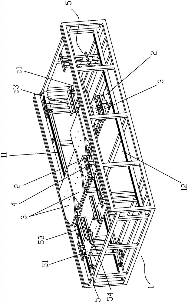
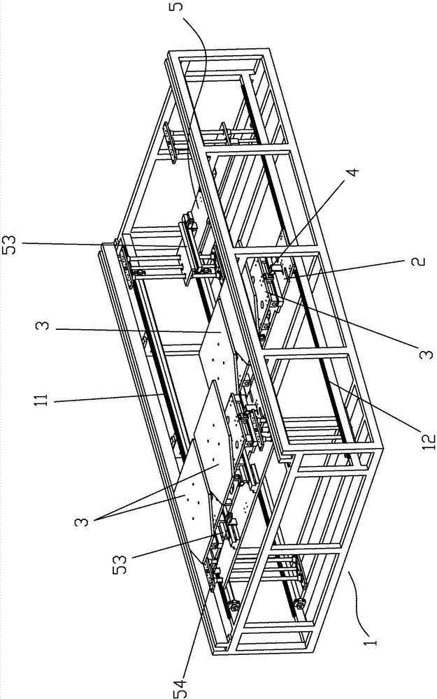
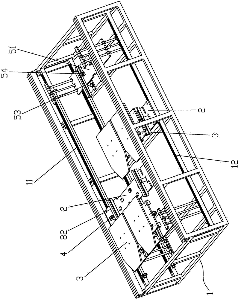
[0027] like Figure 1 to Figure 5 As shown, a circulation feeding mechanism of a printing press includes a frame 1, and the frame 1 includes an upper layer 11 and a lower layer 12 of the frame, and the upper layer 11 of the frame and the lower layer 12 of the frame are respectively provided with A transmission platen 2 that can move back and forth relative to the frame 1. The transmission platen 2 is provided with a movable printing platen 3 that can slide back and forth relative to it and is used to carry printing media. The movable printing platen 3 is connected to the transmission platen. A locking device 4 that can lock the two is provided between the platens 2, and the frame 1 is located on both sides of the transmission platen 2 and is respectively provided with movable printing plates 3 that can transfer the movable printing platen 3 of the upper layer 11 of the fram...


PUM


Abstract

The invention discloses a cycle feeding mechanism of a printing machine, which comprises a frame. The frame includes an upper layer of the frame and a lower layer of the frame. The upper layer of the frame and the lower layer of the frame are respectively equipped with A moving transmission platen, the transmission platen is provided with a movable printing platen that can slide back and forth relative to it and is used to carry printing media, and there is a movable printing platen between the movable printing platen and the transmission platen that can connect the two Locking locking device, the frame is located on both sides of the transmission platen and is respectively equipped with movable printing platen on the upper layer of the frame to the transmission platen on the lower layer of the frame and transfers the movable printing platen on the lower layer of the frame The platen is transferred to the platen transfer device on the transmission platen on the upper layer of the frame. The printing machine adopting the invention has small occupation area, high production efficiency, high degree of automation and low production cost.

Description

【Technical field】 [0001] The invention relates to a printing machine, more specifically to a circulation feeding mechanism of the printing machine. 【Background technique】 [0002] The feeding mechanism of the current printing machine adopts a separate feeding method, that is, the material is loaded at the printing station, and the material is taken out at the printing station after the printing is completed. Therefore, during the printing process of the printing medium, the worker can only wait at the printing station. The production efficiency of such a printing method is very low, the automation level is low, and the production cost is high. In addition, the traditional printing equipment is bulky, especially when it involves multiple stations, and the printing equipment is very long. Therefore, it occupies a very large area, which increases the cost of land and factory buildings for enterprises. [0003] Therefore, the present invention just produces based on above defic...

Claims


Application Information

Patent Timeline
Patent Type & Authority Patents(China)
IPC IPC(8): B65H5/04
CPCB65H5/04B65H2301/36B65H2402/60B41J3/4078
Inventor 何涛
Owner TAOTECH DIGITAL TECH
Why Eureka
Try Eureka