Device for manufacturing rigid tie bar structural member
A technology for making devices and structural parts, applied in auxiliary devices, manufacturing tools, auxiliary welding equipment, etc., can solve the problems of easy errors in welding production, low welding efficiency between T-shaped plates and steel pipes, etc. Improved quality and efficiency, secure clamping effect
- Summary
- Abstract
- Description
- Claims
- Application Information
AI Technical Summary
Problems solved by technology
Method used
Image

Examples
Embodiment 1
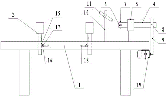
[0027] Such as Figure 2-4 As shown, a manufacturing device for rigid tie rod structural parts of the present invention includes a tie rod welding station 1, a steel pipe bracket 2 and a T-shaped plate clamping rotation assembly 3. The steel pipe bracket 2 is provided on the tie rod welding table 1 , Steel pipes can be placed, the T-shaped plate can be clamped by setting the T-shaped plate clamping rotating assembly 3 on the tie rod welding table 1, and the T-shaped plate can be driven to rotate by the T-shaped plate clamping rotating assembly 3; Two sets of steel pipe brackets 2 are provided on the rod welding table 1. The T-plate clamping rotating assembly 3 includes a rotating shaft 4, a rotating shaft bracket 5 and a motor 19. The rotating shaft bracket 5 is set on the tie rod welding table 1, and the rotating shaft 4 is set Rotate on the rotating shaft support 5, and the middle of the inner end of the rotating shaft 4 is provided with a T-shaped plate clamping groove 6. A ...
Embodiment 2
[0030] Such as Figure 2-4 As shown, the manufacturing device of a rigid tie rod structure of the present invention is based on embodiment 1. The tie rod welding table 1 is provided with a welding torch bracket 10, and a welding torch 11 is mounted on the welding torch bracket 4. Workers can be saved with welding torches, and the quality and efficiency of welding are greatly improved; automatic welding can be realized, which can effectively improve the efficiency of tie rod welding.
Embodiment 3
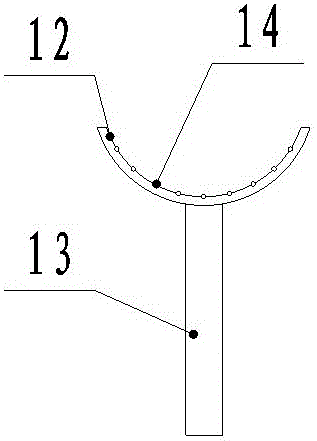
[0032] Such as Figure 2-4 As shown, the present invention is a manufacturing device for rigid tie rod structure. On the basis of embodiment 1, the steel pipe bracket 2 includes an arc bracket 12 for placing steel pipes and a support column 13, and the arc bracket 12 is arranged on the support The upper end of the upright column 13 and the lower end of the supporting upright column 13 are arranged on the tie rod welding table 1. Balls 14 are provided on the inner arc surface of the arc bracket 12.
[0033] The supporting column 13 is installed in the mounting hole provided on the tie-rod welding table 1. One side of the supporting column 13 is provided with a tooth 15 and one side of the mounting hole is provided with a gear 16 that cooperates with the tooth 15 and the gear 16 rotates around the shaft 17. , A hand crank 18 is connected to the rotating shaft 17. The steel pipe bracket 2 is provided with an adjustable height structure, which can adjust the height according to ste...
PUM
 Abstract
Description
Claims
Application Information
 - R&D
- Intellectual Property
- Life Sciences
- Materials
- Tech Scout
- Unparalleled Data Quality
- Higher Quality Content
- 60% Fewer Hallucinations
Browse by: Latest US Patents, China's latest patents, Technical Efficacy Thesaurus, Application Domain, Technology Topic, Popular Technical Reports.
© 2025 PatSnap. All rights reserved.Legal|Privacy policy|Modern Slavery Act Transparency Statement|Sitemap|About US| Contact US: help@patsnap.com