
A hand-held expansion sleeve centering shaving fixture

A hand-held, expanding sleeve technology, which is applied in the direction of gear teeth, gear cutting machines, manufacturing tools, etc., can solve the problems of difficult removal and removal of workpieces, heavy weight, and high precision requirements for positioning aperture dimensions, and achieve improved tooth shape accuracy, reliable positioning, effective centering effect

Active Publication Date: 2018-05-15
XIAN FASHITE AUTOMOBILE TRANSMISSION CO LTD
View PDF14 Cites 0 Cited by
  • Summary
  • Abstract
  • Description
  • Claims
  • Application Information

AI Technical Summary

Problems solved by technology

[0002] At present, the domestic gear processing industry generally uses hand-held fixed mandrel gear shaving fixtures when shaving gears. This type of fixture has a simple structure and is easy to use. Tooth clamps are mainly used on gear shaving machine tools with automatic loading and unloading devices. This type of clamps can be used in gear shaving processes with low positioning hole size accuracy. Its disadvantage is that it is heavy and inconvenient for hand-held operation.
After reviewing relevant literature, it is found that although there are many innovative structural designs in the field of hand-held expansion sleeve centering fixtures in the same industry in China, there are still problems such as unreasonable positioning and clamping actions, and difficult removal of workpieces.

Method used


Image

  • A hand-held expansion sleeve centering shaving fixture

Examples


Embodiment Construction

[0018] The present invention will be further described in detail below in conjunction with specific embodiments, which are explanations of the present invention rather than limitations.

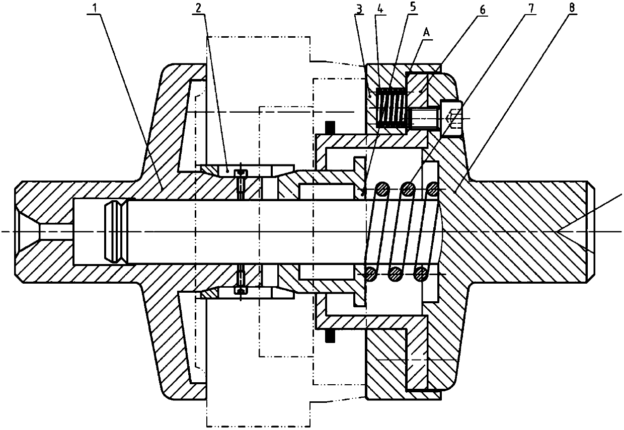
[0019] The present invention is a hand-held expansion sleeve centering gear shaving fixture, such as figure 1 As shown, the static pressure plate 1 and the mandrel 8 cooperate with the left and right tops of the gear shaving machine; the double-cone expansion sleeve 2 connected to the positioning tube cooperates with the static pressure plate 1 and the expansion sleeve gland 5 through the inner cone surface , to tighten the workpiece, the workpiece is indicated by a dotted line in the figure; the static pressure plate 1 and the mandrel 8 are the clearance fit of the hole shaft to ensure that the fixture is concentric with the left and right top of the machine tool; the hanging sleeve 6 and the expansion sleeve gland 5 are the clearance fit of the bore shaft, It plays a position-limiting role;...


PUM


Abstract

The invention provides a handheld type expansion sleeve centering gear-shaving fixture. The gear-shaving fixture comprises a static pressing plate, a double-cone expansion sleeve, a movable pressing plate and a mandrel. A positioning pipe is arranged in the middle portion of the clamping end of the static pressing plate in the axial direction; the mandrel is sleeved with the movable pressing plate, and a first compression spring is arranged between the movable pressing plate and the supporting end face of the mandrel in the axial direction; the mandrel and the inner side of the positioning pipe are in hole axs clearance fit; the mandrel is further sleeved with a centering mechanism for ejecting a workpiece center through hole; a plurality of expansion groove openings are formed in the two ends of the double-cone expansion sleeve, and the inner sides of the two ends of the double-cone expansion sleeve are in inner cone face arrangement with outward large ends; one end of the double-cone expansion sleeve is matched with the outer portion of the positioning pipe for expansion, and the other end of the double-cone expansion sleeve is matched with the centering mechanism for expansion; when a workpiece is clamped, the clamping end of the static pressing plate and the clamping end of the movable pressing plate are used for clamping the two ends of the workpiece, and the other end of the static pressing plate and the mandrel are matched with tips on the same side of a machining tool; and the movable pressing plate is in contact with the clamping end face of the workpiece firstly for pressing and clamping, and the centering mechanism presses one end of the double-cone expansion sleeve for expansion and centering.

Description

technical field [0001] The invention relates to a gear shaving fixture, in particular to a hand-held expansion sleeve centering gear shaving fixture. Background technique [0002] At present, the domestic gear processing industry generally uses hand-held fixed mandrel gear shaving fixtures when shaving gears. This type of fixture has a simple structure and is easy to use. Gear fixtures are mainly used on gear shaving machine tools with automatic loading and unloading devices. This type of fixture can be used in gear shaving processes with low positioning hole size accuracy. Its disadvantage is that it is heavy and inconvenient for hand-held operation. After reviewing relevant literature, it is found that although there are many innovative structural designs in the field of hand-held expanding sleeve centering fixtures in the same industry in China, there are still problems such as unreasonable positioning and clamping actions and difficult removal of workpieces. Contents o...

Claims


Application Information

Patent Timeline
Patent Type & Authority Patents(China)
IPC IPC(8): B23F23/06
CPCB23F23/06
Inventor 冯磊朱变平
Owner XIAN FASHITE AUTOMOBILE TRANSMISSION CO LTD
Learn More