
The power-on control circuit of the airborne laser photometer

An airborne laser and photometer technology, applied in the direction of electrical components, magnetic field/electric field shielding, etc., can solve the problems affecting the heat dissipation of laser power supply, increase the weight of connectors, and reduce the weight of airborne photoelectric stabilization platform, so as to improve stability and use efficiency, improving electromagnetic compatibility performance, and accurate charging completion time

Active Publication Date: 2012-06-27
西安应用光学研究所
View PDF0 Cites 0 Cited by
  • Summary
  • Abstract
  • Description
  • Claims
  • Application Information

AI Technical Summary

Problems solved by technology

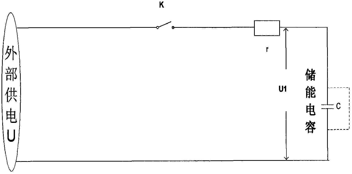
However, there are two problems with this treatment measure: first, it is very difficult to achieve "seamless" shielding treatment; second, after shielding, it will affect the heat dissipation of the laser power supply, which is not conducive to the stable operation of the laser power supply
Another measure adopted in the prior art is to wind the magnetic ring on the cable. Due to the wide frequency band and high energy of the radiation during the charging process, a large number of magnetic rings including various frequency bands are required. In this way, the photoelectric stabilization platform not only needs to increase the magnetic ring The weight of itself, but also increase the weight of a large number of connectors used to fix the magnetic ring, is extremely unfavorable to the weight reduction of the airborne optoelectronic stabilization platform
In addition, the magnetic ring located in the line acts as an inductance device, which will adversely affect the working characteristics of the laser photometer

Method used


Image

  • The power-on control circuit of the airborne laser photometer
  • The power-on control circuit of the airborne laser photometer
  • The power-on control circuit of the airborne laser photometer

Examples


Embodiment Construction

[0018] The present invention will be further described in detail below in conjunction with the accompanying drawings and preferred embodiments.

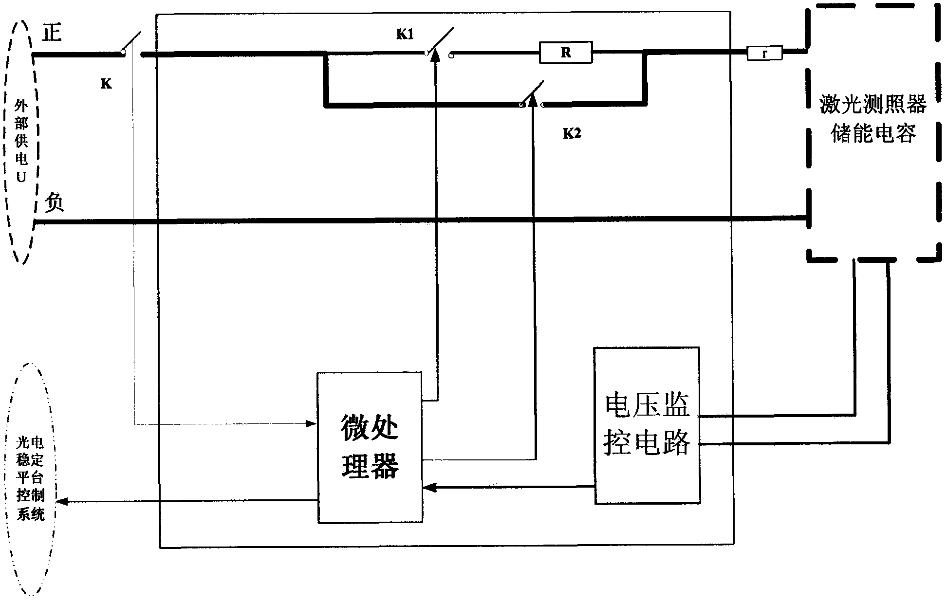
[0019] A certain type of helicopter-borne optoelectronic stabilization platform under research in my country is integrated with a laser photometer, a TV camera and an infrared camera in a limited space. Among them, the laser photometer uses an energy storage capacitor with a capacity of about 1 farad. In order to reduce the interference of the laser photometer to the output signal of the TV camera and infrared camera during the charging process at the moment of power-on, the power-on control circuit of the preferred embodiment of the present invention is used in the charging circuit of the laser photometer.

[0020] according to figure 2 As shown, the power-on control circuit of the preferred embodiment of the present invention includes a first switch K1, a second switch K2, a microprocessor, a voltage monitoring circuit, and a resi...


PUM


Abstract

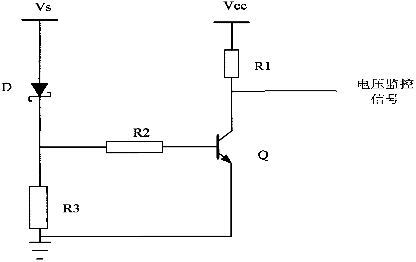
The invention discloses a power-on control circuit of an airborne laser photometer. The main technical content is that a first switch and a resistor are connected in series in the main power line of the laser photometer, and two circuits connected in series connect the two circuits. A second switch is connected in parallel to the end; a voltage monitoring circuit is connected in parallel to the energy storage capacitor of the laser photometer; the microprocessor controls the first and second switches to close and merge according to the power-on signal of the laser photometer and the effective signal of the voltage monitoring circuit. Send the charging completion information to the superior control system. The invention can connect the resistance into the main power line when the energy storage capacitor is charged, and separate the resistance from the main power line after the charging is completed, thus greatly reducing the current change rate of the laser photometer at the moment of power-on, effectively reducing the The external electromagnetic radiation of the main power line of the laser photometer improves the electromagnetic compatibility between the sensors of the airborne photoelectric stabilization platform.

Description

technical field [0001] The invention belongs to the technical field of electromagnetic compatibility, and mainly relates to the electromagnetic compatibility problem between photoelectric sensors on an airborne photoelectric stabilization platform, in particular to a power-on control circuit capable of reducing electromagnetic interference generated at the moment of charging a laser photometer. Background technique [0002] The optoelectronic stabilized platform is a kind of optoelectronic equipment installed on the moving carrier (weapon platform) to search, aim, track, illuminate and measure the target. Due to the requirements of optical parallelism, the laser photometer must be integrated with sensors such as TV and infrared camera, and installed in the turret of the photoelectric stabilization platform. After the target is found through the TV and infrared camera, the laser photometer is turned on for target detection Instructions to achieve the strike on the target. Si...

Claims


Application Information

Patent Timeline
Patent Type & Authority Patents(China)
IPC IPC(8): H05K9/00
Inventor 李阳刘召庆惠渭生许辉李剑敏徐静
Owner 西安应用光学研究所
Learn More