Markers, phantoms and associated methods for calibrating imaging systems

A medical imaging system and marker technology, applied in the field of medical imaging, can solve problems such as errors

Active Publication Date: 2016-06-08
ELEKTA AB
View PDF4 Cites 5 Cited by
  • Summary
  • Abstract
  • Description
  • Claims
  • Application Information

AI Technical Summary

Problems solved by technology

Replacing ball bearings with MR imaging markers introduces a potential source of error if the two markers are not precisely colocalized within the phantom
Furthermore, the translation of the phantom between the two devices introduces an additional source of error

Method used


Image

  • Markers, phantoms and associated methods for calibrating imaging systems
  • Markers, phantoms and associated methods for calibrating imaging systems
  • Markers, phantoms and associated methods for calibrating imaging systems

Examples


Embodiment Construction

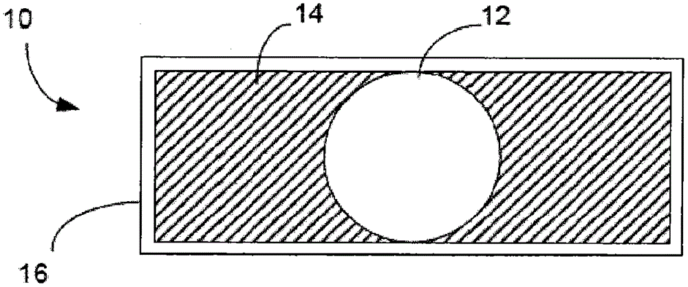
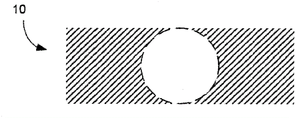
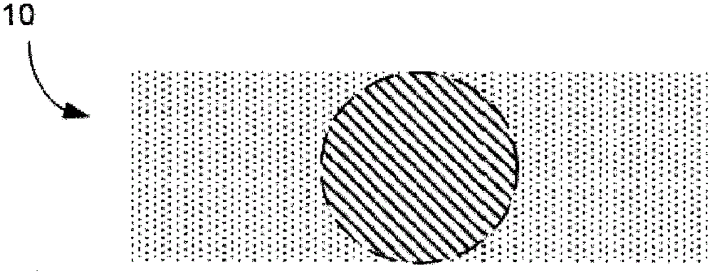
[0020] figure 1 A cross-section of a marker 10 according to an embodiment of the invention is shown. As will be explained below, marker 10 is suitable for use with various medical imaging systems using different imaging modalities.

[0021] To understand how markers work, it is instructive to first consider the different imaging mechanisms that can be employed in medical imaging.

[0022] Magnetic resonance (MR) imaging works by exposing the imaged subject to a high-strength magnetic field. Currently, field strength densities typically vary from system to system between 0.2 and 3T. In this strong magnetic field, the magnetic moments of the hydrogen protons in the object become aligned with the magnetic field. By applying an electromagnetic signal with a resonant frequency to the object, the spins of those protons are flipped. When the electromagnetic signal is turned off, the protons flip back and emit an electromagnetic signal that can be picked up by the receiver coil. ...


PUM


Abstract

Embodiments of the present invention provide markers, phantoms, and associated methods of calibration which are suitable for use in both medical resonance imaging and radiographic imaging systems. A marker (10) includes a first component (12) having a first hydrogen proton density and a first mass density; and a second component (14) having a second hydrogen proton density different than the first hydrogen proton density, and a second mass density different than the first mass density. The first and second components are non magnetic.

Description

technical field [0001] The present invention relates to medical imaging, and more particularly to markers, phantoms and associated methods for calibrating imaging systems that can be integrated with radiation therapy systems. Background technique [0002] Recent developments in the field of radiation therapy have focused on integrating imaging systems with treatment systems. The goal is to provide real-time feedback on the location of an anatomical feature in the patient, such as a tumor, so that the therapeutic radiation beam can be more precisely steered to target that feature. [0003] One proposed approach combines a linear accelerator-based therapy system with a magnetic resonance imaging (MRI) system within a single device called the MRI-Linac. This device is described in various earlier applications of the present applicant, including US Patent Application No. 12 / 704,944 (Publication No. 2011 / 0201918) and PCT Publication No. 2011 / 127947. In the systems described in ...

Claims


Application Information

Patent Timeline
Patent Type & Authority Applications(China)
IPC IPC(8): A61B90/00G01R33/58A61B17/00
CPCG01R33/58A61B2017/00707A61B2017/00725G01R33/4808A61B2090/3995A61B90/39A61B2090/3954A61B2090/3966A61B6/582G01R33/4812A61B6/584A61B6/583A61N5/1075A61N2005/1076
Inventor M·塞尔D·米尔斯J·拜尔恩J·阿伦D·A·罗伯茨
Owner ELEKTA AB
Why Eureka
Try Eureka