Housing and housing removal machine

A shell and machine technology, applied in the direction of electrical equipment shell/cabinet/drawer, electrical components, etc., can solve the problems of high price of mold release agent and epoxy material, unsuitable for automatic machine operation, air bubbles affecting pressure resistance, etc. The filling labor cost is low, the possibility of scratches is reduced, and the product has good pressure resistance.

Inactive Publication Date: 2016-06-08
朱佳瑞
View PDF0 Cites 2 Cited by
  • Summary
  • Abstract
  • Description
  • Claims
  • Application Information

AI Technical Summary

Problems solved by technology

[0002] Miniaturization is the general pursuit of components. Currently, the components used in the market, such as capacitors, transformers, inductors, Hall devices, optocouplers, photoelectric switches, relays and transformers, are generally encapsulated with internal epoxy and plastic shells. The method of production, but the shell must occupy a certain volume. For devices with small volume requirements, only the volume of the shell can be reduced. The problem is that it is difficult to pack the inner core into the shell. The shelling process may damage the inner core and increase the cost of the shell. Working hours, epoxy potting is difficult and air bubbles affect the pressure resistance performance, the shell material requires environmental protection and flame retardancy, and the material cost is high
[0003] Epoxy encapsulation can also be carried out with shellless encapsulation technology. The disadvantage is that it is necessary to open the mold, the cost of the mold is high, and there are also the disadvantages of high price of release agent and epoxy material during epoxy potting, complicated operation and high man-hours.
[0004] I have applied to add some grooves to the outer shell of the transformer. It is not a transformer shell with only one groove and no ears. The disadvantage is that it needs to be disassembled many times, and the dismantling takes a lot of man-hours, which is not suitable for machine automation.

Method used


Image

  • Housing and housing removal machine
  • Housing and housing removal machine
  • Housing and housing removal machine

Examples


Embodiment 1

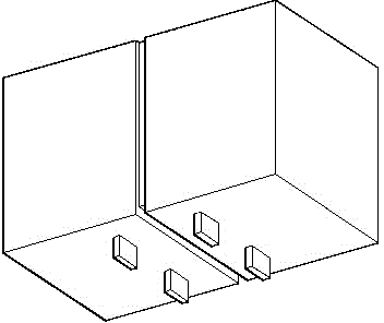
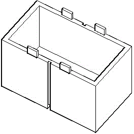
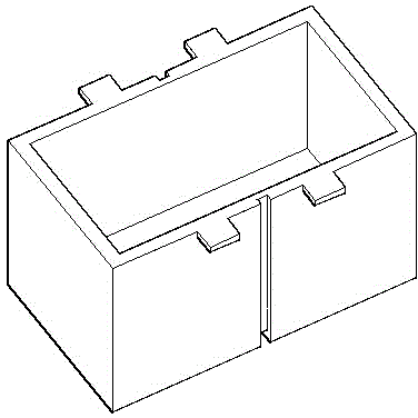
[0029] Put the inner core into figure 1 with 2 In the transformer, after the epoxy potting and curing is completed, put the transformer into the vibrating plate, and after screening, the transformers are arranged in an orderly manner with the pins facing upward and the bottom of the shell downward, entering such as Figure 8 In the shown rails, screened into an orderly arrangement of matching grooves along the bottom ears, along the rails into the dehulling machine's Figure 9 with 10 In the groove of the gripper, the gripper moves to the two sides, the outer shell is torn off, and the finished transformer with epoxy as the outer part falls into the finished product box, and this implementation is completed.

Embodiment 2

[0031] Put the inner core into figure 1 with 2 In the square transformer, after the epoxy potting and curing is completed, use two vices to clamp the ears on both sides of the groove respectively, tear the shell along the groove, and leave the transformer without a shell encapsulated by epoxy. To complete this implementation, of course, if the manpower is large, you can also use two vices to clamp the ears on both sides of the bottom groove, tear the shell along the groove, and leave the transformer without a shell encapsulated by epoxy to complete this implementation.

Embodiment 3

[0033] Put the inner core into Figure 4 with 5 In the cylindrical transformer, after the epoxy potting and curing is completed, use two vices to clamp the ears on both sides of the groove respectively, tear the shell along the groove, and leave the transformer without a shell encapsulated by epoxy , to complete this implementation.


PUM


Abstract

The invention discloses an electrical component housing. The housing is externally provided with a slit penetrating the housing, the two sides of the slit are provided with some lugs, after epoxy embedding is finished, the lugs at the two sides of the slit are drawn towards two directions, the housing is removed, and thus a housing-free packaging effect is realized. A matched vibration disc and a removal machine are designed. The invention provides a method for removing the housing by finishing epoxy formation with assistance of a plastic housing and then drawing the lugs at the two sides of the slit penetrating the housing at the outside of the housing. The advantages are as follows: the cost is low and the implementation is easy.

Description

technical field [0001] The invention relates to an electrical component, in particular to a plastic shell of the electrical component requiring epoxy encapsulation. Background technique [0002] Miniaturization is the general pursuit of components. Currently, the components used in the market, such as capacitors, transformers, inductors, Hall devices, optocouplers, photoelectric switches, relays and transformers, are generally encapsulated with internal epoxy and plastic shells. The method of production, but the shell must occupy a certain volume. For devices with small volume requirements, only the volume of the shell can be reduced. The problem is that it is difficult to pack the inner core into the shell. The shelling process may damage the inner core and increase the cost of the shell. During the working hours, epoxy potting is difficult and air bubbles affect the pressure resistance performance. The shell material is required to be environmentally friendly and flame-ret...

Claims


Application Information

Patent Timeline
Patent Type & Authority Applications(China)
IPC IPC(8): H05K5/00
Inventor 朱佳瑞
Owner 朱佳瑞
Why Eureka
Try Eureka