Mixed light dimming circuit and mixed light dimming method used for LED

A hybrid dimming and dimming control circuit technology, which is applied in the field of LED dimming, can solve the problems of large proportion, poor accuracy of the lowest point of dimming, and the brightness of LED lights cannot be made very dark, so as to improve the depth of dimming , Good effect of dimming precision

Active Publication Date: 2016-06-08
SILERGY SEMICON TECH (HANGZHOU) CO LTD
View PDF5 Cites 17 Cited by
  • Summary
  • Abstract
  • Description
  • Claims
  • Application Information

AI Technical Summary

Problems solved by technology

[0004] However, the disadvantages of the above-mentioned dimming method are: 1) Due to the inherent bias of the operational amplifier, there is a fixed deviation (assuming 20mV) between the current feedback signal and the reference amplitude signal. When the duty cycle D is very small, the proportion is very large (for example, the reference voltage signal Vreference=1V, then when the duty cycle D of the PWM dimming control signal is 5%, the obtained reference amplitude signal is: D×Vreference= 50mV, 20mV has a large proportion to 50mV), that is, the accuracy of the lowest point of dimming is very poor
[0005] 2) Due to the large bias of the op amp, the dimming depth cannot generally be made very low. At this time, the output current is still relatively large, and the brightness of the LED light cannot be made very dim.

Method used


Image

  • Mixed light dimming circuit and mixed light dimming method used for LED
  • Mixed light dimming circuit and mixed light dimming method used for LED
  • Mixed light dimming circuit and mixed light dimming method used for LED

Examples


Embodiment Construction

[0062] Several preferred embodiments of the present invention will be described in detail below with reference to the accompanying drawings, but the present invention is not limited to these embodiments. The present invention covers any alternatives, modifications, equivalent methods and arrangements made within the spirit and scope of the present invention. In order to give the public a thorough understanding of the present invention, specific details are described in detail in the following preferred embodiments of the present invention, and those skilled in the art can fully understand the present invention without the description of these details.

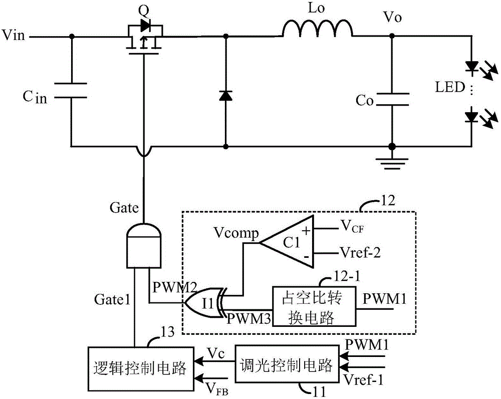
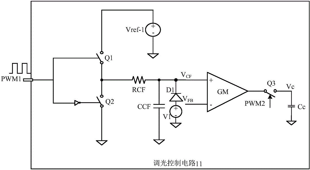
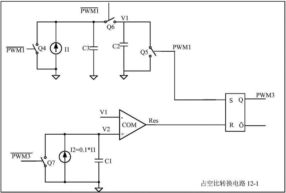
[0063] refer to figure 1 Shown is the principle block diagram of the hybrid dimming circuit according to the present invention, the hybrid dimming circuit is used to drive the LED lamp load, and the hybrid dimming circuit includes a power stage circuit, a dimming control circuit 11, a conversion control circuit 12 and Logic co...


PUM


Abstract

The invention discloses a mixed light dimming circuit and mixed light dimming method used for an LED. When the duty ratio of an external first light dimming signal is larger than or equal to a preset value N, light dimming is performed in an amplitude light dimming mode; when the duty ratio of the first light dimming signal is smaller than the preset value N, the duty ratio of the first light dimming signal is converted through a duty ratio conversion circuit so that a second light dimming signal can be acquired, and then light dimming is performed in an ON-OFF light dimming mode. According to the mixed light dimming method, when a PWM1 light dimming signal is large in duty ratio, light dimming precision is good, output current has light fluctuation, output current is adjusted in an ON-OFF light dimming mode by means of conversion under the condition that the duty ratio of the PWM1 light dimming signal is very small, and therefore the light dimming depth can be increased.

Description

technical field [0001] The invention relates to the field of LED dimming, and more particularly, to a hybrid dimming circuit and a hybrid dimming method. Background technique [0002] LED lights have the characteristics of small size, high mechanical strength, low power consumption, long life, easy adjustment and control, and no pollution. It is a new type of light source product with great development prospects. There are different requirements for dimming of LED lights in different occasions. In order to adapt to different occasions, the requirements for dimming of LED lights are generally: good linearity, wide dimming range, high stability, high power factor, Low electromagnetic interference, low cost, etc., so LED drivers with excellent dimming performance are very important. [0003] The traditional LED dimming usually has an amplitude dimming method. The principle is: the PWM dimming control signal is input into the control chip through the pins, and the control chip ...

Claims


Application Information

Patent Timeline
Patent Type & Authority Applications(China)
IPC IPC(8): H05B33/08H05B44/00
CPCH05B45/00
Inventor 王建新陈惠强
Owner SILERGY SEMICON TECH (HANGZHOU) CO LTD
Why Eureka
Try Eureka