
Automatic automobile waxing machine

An automatic and automotive technology, applied in vehicle maintenance, vehicle maintenance/repair, transportation and packaging, etc., can solve the problems of different thickness of wax on the car body, affect the appearance of the car body, wax melting or condensation, etc., to improve the appearance of waxing performance, improved waxing efficiency, consistent waxing effect

Inactive Publication Date: 2016-06-08
江苏创迈达智能科技有限公司
View PDF6 Cites 2 Cited by
  • Summary
  • Abstract
  • Description
  • Claims
  • Application Information

AI Technical Summary

Problems solved by technology

[0002] Nowadays, cars have gradually become a necessary tool for people's transportation and life. Cars need regular maintenance when they are in use, and waxing is one of the basic maintenance for car maintenance. Most of the car maintenance on the market is manual waxing. Artificial waxing has many disadvantages: First, the strength of waxing cannot be controlled, and excessive force in some areas will cause damage to the car paint. Uneven strength during waxing will make the thickness of the car body waxed different, affecting the appearance of the car body; secondly , the amount of wax applied is uneven, and when the amount of wax applied is too small, the wear of the car paint will be accelerated; in addition, it needs to be dried for 5-10 minutes after manual waxing. During this process, dust is easily embedded in the wax and wears the car In addition, waxing also requires a suitable temperature. If the temperature is too high or too low, it will easily melt or condense the wax, which is not conducive to uniform waxing. It can be seen that the current waxing on the market There are many deficiencies in the method and need to be improved

Method used


Image

  • Automatic automobile waxing machine
  • Automatic automobile waxing machine
  • Automatic automobile waxing machine

Examples


Embodiment

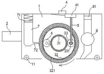
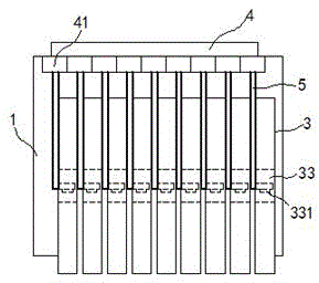
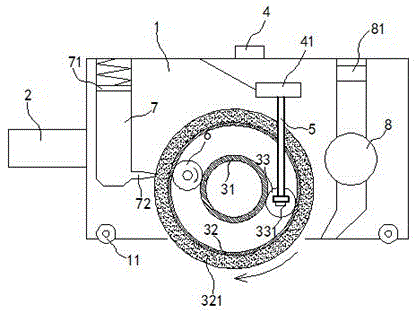
[0019] exist Figure 1 to Figure 4 In the shown embodiment, the automobile automatic waxing machine includes a housing 1 and a handle 2, and the handle 2 is fixedly mounted on the side wall of the housing 1; Wheel 3, described waxing wheel 3 coaxial, parallel arrangement; Described waxing wheel 3 comprises inner wheel 31, outer wheel 32 and transmission wheel 33, and described inner wheel 31 and outer wheel 32 are concentric structures, and described transmission The wheel 33 is located between the inner wheel 31 and the outer wheel 32, and is tangent to the inner wheel 31 and the outer wheel 32; a waxing sponge 321 is fixedly adhered to the outer peripheral surface of the outer wheel 32; A distance sensor 331; a controller 4 is installed on the housing 1, and each distance sensor 331 is electrically connected to the controller 4; the controller 4 includes a controller corresponding to each waxing wheel 3 end 41, a transmission rod 5 is also installed on each of the transmiss...


PUM


Abstract

The invention relates to an automatic automobile waxing machine. The automatic automobile waxing machine comprises a shell and a handle. The handle is fixedly installed on the side wall of the shell. A set of waxing wheels is installed in the shell. Each waxing wheel comprises an inner wheel body, and outer wheel body and a transmission wheel body, and the transmission wheel body is located between the inner wheel body and the outer wheel body and is tangent to the inner wheel body and the outer wheel body. A controller is installed on the shell. All distance sensors are electrically connected with the controller. The controller comprises control ends corresponding to all the waxing wheels. All the transmission wheel bodies are provided with transmission rods which are connected to the control ends of the controller correspondingly. A driving roller driven by a driving motor is installed in the shell and sequentially penetrates through the parts, between the inner wheel bodies and the outer wheel bodies, of all the waxing wheels. The driving roller can simultaneously drive the inner wheel bodies and the outer wheel bodies to rotate. A wax storage cavity is installed in the shell and filled with wax liquor. A nozzle of the wax storage cavity is attached to all waxing sponges.

Description

technical field [0001] The invention relates to a waxing machine, in particular to an automatic waxing machine. Background technique [0002] Nowadays, cars have gradually become a necessary tool for people's transportation and life. Cars need regular maintenance when they are in use, and waxing is one of the basic maintenance for car maintenance. Most of the car maintenance on the market is manual waxing. Artificial waxing has many disadvantages: First, the strength of waxing cannot be controlled, and excessive force in some areas will cause damage to the car paint. Uneven strength during waxing will make the thickness of the car body waxed different, affecting the appearance of the car body; secondly , the amount of wax applied is uneven, and when the amount of wax applied is too small, the wear of the car paint will be accelerated; in addition, it needs to be dried for 5-10 minutes after manual waxing. During this process, dust is easily embedded in the wax and wears th...

Claims


Application Information

Patent Timeline
Patent Type & Authority Applications(China)
IPC IPC(8): B60S5/00
CPCB60S5/00
Inventor 顾钰锋
Owner 江苏创迈达智能科技有限公司
Learn More