
Cutting and receiving system of a laser cutting machine

A laser cutting machine and cutting system technology, applied in laser welding equipment, welding equipment, metal processing equipment, etc., can solve the problems of uneven transmission, insufficient rigidity, deviation of finished product shape and size, etc., and achieve stable transmission and cutting quality. Good results

Active Publication Date: 2018-02-16
CHERY AUTOMOBILE CO LTD
View PDF6 Cites 0 Cited by
  • Summary
  • Abstract
  • Description
  • Claims
  • Application Information

AI Technical Summary

Problems solved by technology

[0003] Although the cutting system of the existing laser cutting machine can meet the functional requirements and cut according to the trajectory path designed by the computer, according to the debugging process and the feedback from existing customers, it is found that the cutting system of the existing laser cutting machine has many shortcomings in terms of performance, such as : The cutting cannot be completely cut through, the table shakes when cutting, the shape and size of the finished product after cutting are deviated, especially the arc corners have sawtooth, etc.
[0004] The support in the reclaiming system of the existing laser cutting machine is in the form of a gantry. The rodless cylinder is offset on one side, and one side is a linear guide rail. The torsional strength is not enough, the manipulator has a small angle of torsion, and a guide rod needs to be added. The main defects are as follows: 1. Although the existing reclaiming system can meet the requirements of retrieving materials, it is difficult to control accurately, the power is unbalanced, and the transmission is not stable. , sometimes causing the pole piece to drop, damage, and affect the subsequent work cycle; 2. Although the double-rod lifting cylinder can meet the output force requirements, but the rigidity is insufficient, affecting the stability of the work

Method used


Image

  • Cutting and receiving system of a laser cutting machine
  • Cutting and receiving system of a laser cutting machine
  • Cutting and receiving system of a laser cutting machine

Examples


Embodiment 1

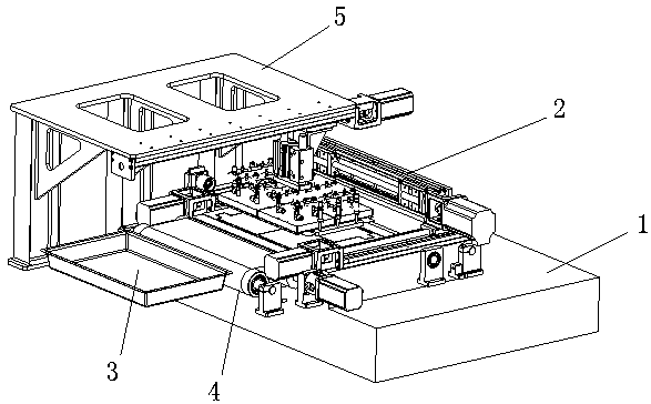
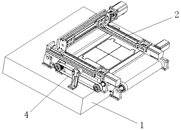
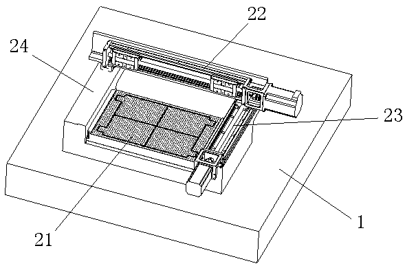
[0028] As shown in the figure, the cutting and receiving system of the laser cutting machine of this embodiment includes a base 1 provided with a cutting system 2, and a finished product tray 3 is provided on the side of the base 1, and the base 1 is placed on the side of the cutting system 2. A conveying unit 4 is provided below, and a reclaiming system 5 is provided above the cutting system 2. The cutting and receiving system of the laser cutting machine also includes a controller for controlling the conveying unit 4, the cutting system 2 and the reclaiming system 5 The key point is that the base 1 is also provided with a proximity switch for detecting whether there is a raw material tape in the cutting area; the controller is connected to the proximity switch (the controller and the proximity switch are not shown in the figure).

[0029] Specifically, the cutting system 2 includes a support, a moving cutting assembly mounted on the support 24, and an adsorption assembly 21. ...


PUM


Abstract

The invention provides a cutting and collecting system of a laser cutting machine. The cutting and collecting system of the laser cutting machine aims to improve the cutting effect and the collecting effect and comprises a base with a cutting system, a finished product tray is arranged beside the base, and a conveying unit and a picking system are arranged above the base. The cutting and collecting system of the laser cutting machine further comprises a controller used for controlling the conveying unit, the cutting system and the picking system and is characterized in that the base is provided with a proximity switch used for detecting whether raw material strips exist in a cutting area and the controller is connected to the proximity switch. According to the cutting and collecting system of the laser cutting machine, the cutting system, the picking system and the conveying unit are improved, the raw material strips are conveyed more stably, the cutting quality is higher, and finished products of pole pieces are prevented from being damaged in the picking process; the proximity switch is additionally arranged and can detect the condition of the raw material strips in the cutting area in real time, and therefore the work can be carried out automatically and continuously.

Description

technical field [0001] The invention belongs to the technical field of mechanical processing equipment, and in particular relates to a cutting and receiving system of a laser cutting machine. Background technique [0002] The cutting system of the laser cutting machine is its most important part. Its main function is cutting. First of all, it must be ensured that the entire cutting movement can be completed according to the input trajectory, and other undesirable movements such as overshoot and overtravel will not occur. In addition, It is also necessary to be able to accurately and timely determine whether the material tape is in place before cutting, to be able to firmly absorb the raw materials at all times during cutting for cutting, and to be able to accurately and timely determine whether the finished product is taken away after cutting, and whether it can start The next loading is to realize the continuous operation of the laser cutting machine. The main performance ...

Claims


Application Information

Patent Timeline
Patent Type & Authority Patents(China)
IPC IPC(8): B23K26/38B23K26/08B23K26/70
CPCB23K26/0838B23K26/0876B23K26/38
Inventor 江涛朱志军
Owner CHERY AUTOMOBILE CO LTD
Learn More