Deironing device for foundry sand

A technology of foundry sand and electromagnets, which is applied in foundry molding equipment, manufacturing tools, machinery for cleaning/processing of mold materials, etc., can solve problems such as insufficient iron removal, impact on the performance of casting workpieces, and falling iron filings. , to achieve complete iron removal, high reliability and good effect.

Inactive Publication Date: 2016-06-08
ANHUI YONGCHANG CASTING
View PDF7 Cites 0 Cited by
  • Summary
  • Abstract
  • Description
  • Claims
  • Application Information

AI Technical Summary

Problems solved by technology

Casting sand must be treated with iron removal before use, otherwise it will have a great impact on the performance of the cast workpiece. The existing iron removal device for foundry sand is relatively simple, and it is generally used in the process of transportation. Iron removal is carried out above the conveyor belt. This iron removal is not thorough enough, because iron wires or iron filings may be buried at the bottom of the sand, and the magnet may not have enough suction to suck them out. If there are more iron filings, it should be cleaned regularly, otherwise it will easily cause the iron filings to fall when more iron filings are absorbed.

Method used


Image

  • Deironing device for foundry sand
  • Deironing device for foundry sand

Examples


Embodiment Construction

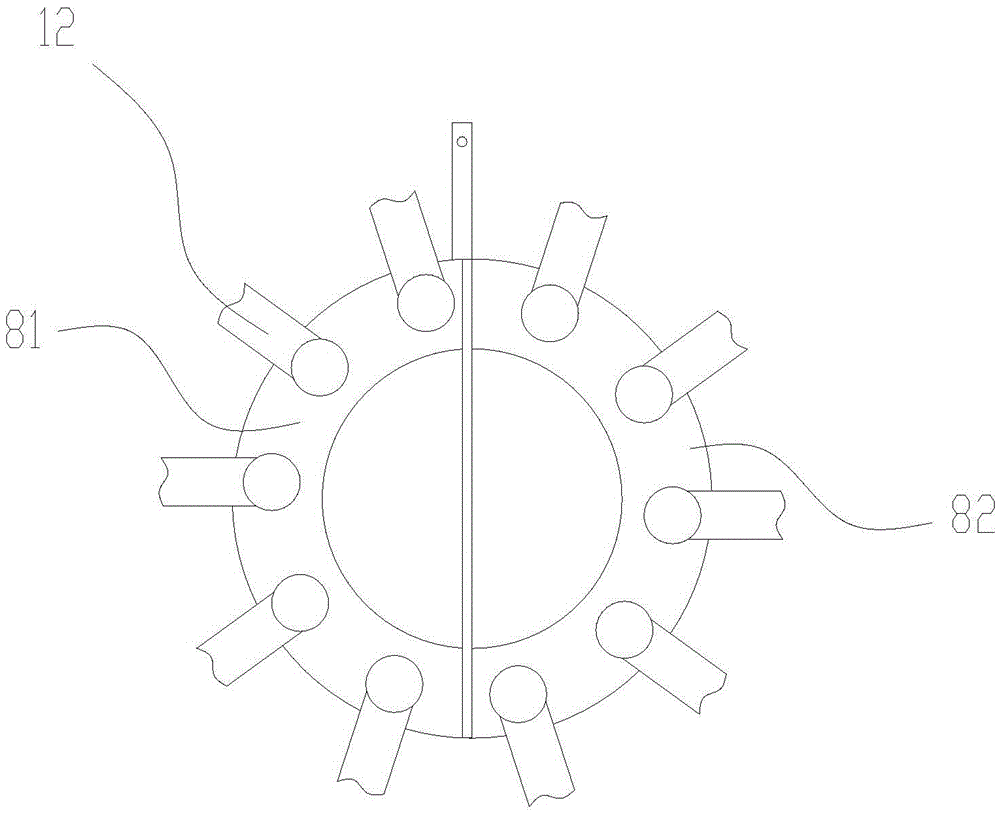
[0012] In order to make the technical means, creative features, goals and effects achieved by the present invention easy to understand, the present invention will be further described below in conjunction with specific illustrations.

[0013] Such as figure 1 with 2 As shown, a casting sand iron removal device includes a conveyor frame 1, a conveyor belt 2, a dial wheel 3, a dial motor 4, an electromagnet wheel 5, an electromagnet 6, a transmission motor 7, a butterfly plate 8, and a receiving box 9 And the brush 10, the conveyor belt 2 is set on the conveyor frame 1 through the conveyor roller, the dial wheel 3 is rotatably arranged on the conveyor frame 1 and is located on the upper side of the conveyor belt 2, and the dial motor 4 is fixedly arranged on the conveyor frame 1 And connected with dial 3 transmissions, electromagnet wheel 5 is rotatably arranged on the conveying frame 1 by wheel bracket 11 and is positioned at the rear side upper position of dial 3, and electro...


PUM


Abstract

The invention discloses a deironing device for foundry sand and relates to the technical field of foundry sand processing. The deironing device comprises a conveying rack, a conveying belt, a dial wheel, a dial wheel motor, an electromagnet wheel, electromagnets, a driving motor, a disc, a material receiving box and brush, wherein the conveying belt is arranged on the conveying rack through conveying rollers; the dial wheel is rotatably arranged on the conveying rack and located on the upper side of the conveying belt; the dial wheel motor is fixedly arranged on the conveying rack and is in transmission connection with the dial wheel; the electromagnet wheel is rotatably arranged on the conveying rack through a wheel support, and the electromagnets are uniformly arranged on the surface of the electromagnet wheel; the driving motor is in transmission connection with the electromagnet wheel; the disc is fixedly arranged on the wheel support and located at the position of the shaft end of the electromagnet wheel; end sides of the electromagnets are connected with the disc in a slideable mode through metal sheets respectively; the material receiving box is fixedly arranged on the conveying rack; and the brush is fixedly arranged on the conveying rack through a brush support. The deironing device is convenient to use; iron is removed thoroughly; the effect is excellent; the device needs not to be cleaned for a long time; and the use reliability is high.

Description

Technical field: [0001] The invention relates to the technical field of casting sand treatment, in particular to a casting sand iron removal device. Background technique: [0002] It is a granular refractory material used to prepare molding sand and core sand in foundry production. In the case of using clay as the sand binder, about 1 ton of new sand is needed to produce 1 ton of qualified castings, so the amount of foundry sand is the largest in sand casting production. Casting sand must be treated with iron removal before use, otherwise it will have a great impact on the performance of the cast workpiece. The existing iron removal device for foundry sand is relatively simple, and it is generally used in the process of transportation. Iron removal above the conveyor belt is not thorough enough, because iron wire or iron filings may be buried at the bottom of the sand, and the magnet may not have enough suction to suck it out. In addition, the outside of the long-term used ...

Claims


Application Information

Patent Timeline
IPC IPC(8): B22C5/06
CPCB22C5/06
Inventor 李新
Owner ANHUI YONGCHANG CASTING
Why Eureka
Try Eureka