
Cable striping pincers and stripping method therefor

A cable and pliers body technology, applied in the field of cable stripping pliers and stripping, can solve the problems of inability to achieve axial stripping, unadjustable axial length, and inability to strip cables, and achieve simple structure and method, strong versatility, Easy to use effect

Active Publication Date: 2016-06-01
GUANGZHOU PANYU CABLE WORKS
View PDF6 Cites 2 Cited by
  • Summary
  • Abstract
  • Description
  • Claims
  • Application Information

AI Technical Summary

Problems solved by technology

However, there are still the following defects: one, the wire stripper realizes that the circumferential direction of the cable is stripped, and the axial stripping still cannot be realized.
The third is that there is only a pair of vertical blades. When using it, you need to cut the cable at one position first, then measure the size manually and then cut another position, which is inefficient.
Fourth, the axial length is not adjustable, and the cable cannot be stripped according to actual needs

Method used


Image

  • Cable striping pincers and stripping method therefor
  • Cable striping pincers and stripping method therefor
  • Cable striping pincers and stripping method therefor

Examples


Embodiment 1

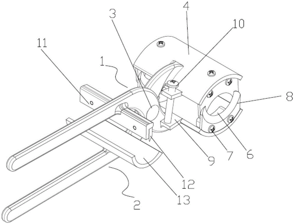
[0041] like figure 1 As shown, a cable stripping pliers includes an upper pliers body 1 and a lower pliers body 2 hinged through a pin shaft 3, and a pliers head is respectively formed at the front end of the hinge point of the upper pliers body 1 and the lower pliers body 2, and at the hinge point A pliers handle is formed at the rear end of the pliers respectively, and a transverse blade 12 for axial peeling is fixed on the upper pliers body 1 or the lower pliers body 2 .

[0042] Wherein, a transverse blade 12 for axial peeling is fixed on the inner side of the forceps head of the upper forceps body 1 or the inner side of the forceps head of the lower forceps body 2, and the inner side of the forceps handle of the upper forceps body 1 and the forceps handle of the lower forceps body 2 are fixed A vertical blade 8 for circumferentially peeling the cable is fixed on the inner side, and the vertical blade 8 fixed on the clamp handle of the upper clamp body 1 and the vertical b...

Embodiment 2

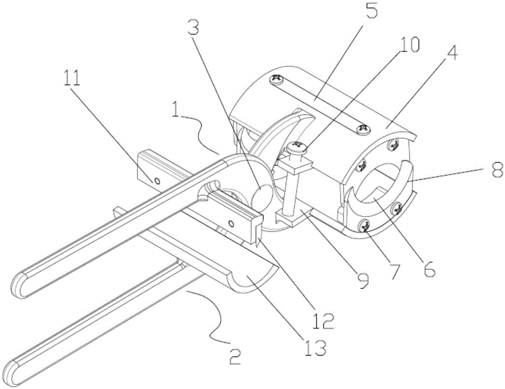
[0057] like figure 2 As shown, this embodiment adds an axial peeling length adjustment structure of the vertical blade 8 on the basis of the first embodiment. The fixing bolts 7 of 5 are fixed on the connecting piece 4 on the corresponding pliers body in the upper pliers body 1 and the lower pliers body 2, and the connecting block 6 can slide on the connecting piece 4 along the length direction of the guide groove to adjust the connecting piece 4. The distance between the two connecting blocks 6 can be adjusted to realize the peeling length.

Embodiment 3

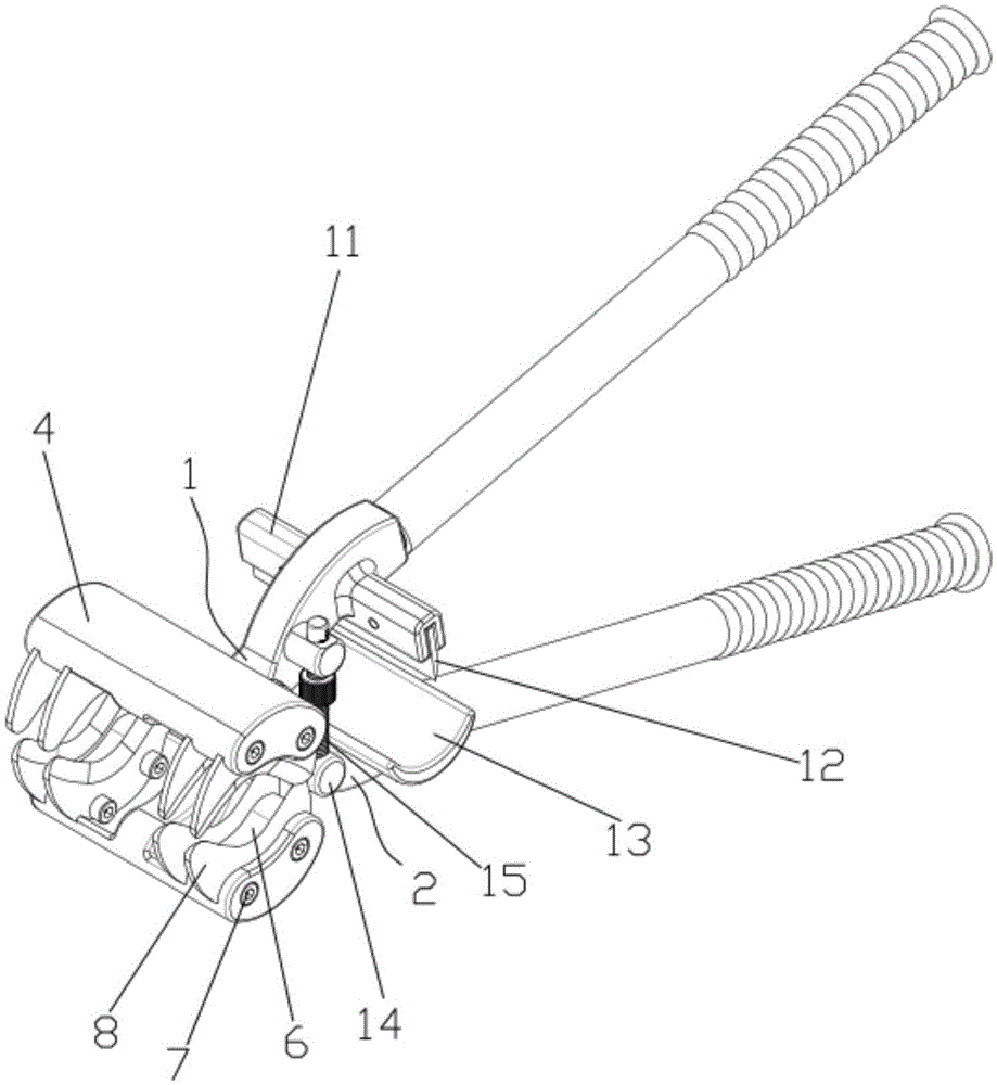
[0059] like image 3 As shown, this embodiment is provided with an axial peeling length adjustment structure that is different from the vertical blade in Example 2. The adjustment structure includes that a plurality of vertical blades 8 corresponding to each other are arranged on the connecting block 6, so that the peeling length can be adjusted. tune.

[0060] like image 3 As shown in the figure, this embodiment is provided with a peeling depth adjustment structure that is different from that in Embodiment 1 and Embodiment 2. The adjustment structure includes that both the upper jaw body 1 and the lower jaw body 2 are provided with A cylinder 14 with a threaded hole, and at least one cylinder 14 is hinged with the pliers head on which the cylinder 14 is provided, or a cylinder with a threaded hole is provided on the pliers handle of the upper pliers body 1 and the pliers handle of the lower pliers body 2 14, and at least one cylinder 14 is hinged with the clamp handle on w...


PUM


Abstract

The invention discloses a pair of cable striping pincers, which comprises an upper pincer body and a lower pincer body, wherein the upper pincer body and the lower pincer body are hinged with each other through a pin shaft; pincer heads are formed at the front ends of the hinged points of the upper pincer body and the lower pincer body; pincer handles are formed at the rear ends of the hinged points; and a transverse blade for axial stripping is fixed on the upper pincer body or the lower pincer body. The method further discloses a stripping method for the cable striping pincers. The method can achieve cable stripping in the circumferential direction and the axial direction and can also achieve length stripping of the cable through a guide groove or a mounting hole on a connector. The method also comprises a step of adjusting an adjusting bolt or a stud or a limiting block to achieve depth stripping of the cable. The structure and the method disclosed by the invention are simple, simple and convenient to operate and high in efficiency, can be suitable for cables with various wire diameters, can achieve stripping in the circumferential direction and the axial direction, can even adjust the stripping depth and length and can warn that a knife edge is in contact a wire core to protect the wire core.

Description

technical field [0001] The invention relates to the field of electric tools, in particular to a cable stripping pliers and a stripping method thereof. Background technique [0002] When an electrician installs or overhauls a power cable, he needs to peel off the insulation layer covered by the cable to connect the line. Traditional cable stripping tools use tools such as electrician's knife, hook knife or wallpaper knife to peel off the skin. Since the cable is usually placed in the air, And the cable insulation layer is thicker and harder. Electricians often need to apply a lot of force to peel off the cable sheath during the operation. This process is likely to cause injury to the electrician and damage the internal structure of the cable. Therefore, this type of stripping tool is used It is extremely unsafe to strip the cable. [0003] The currently used stripping pliers include two pliers handles that are hinged up and down. The upper pliers handle is equipped with an i...

Claims


Application Information

Patent Timeline
IPC IPC(8): H02G1/12
CPCH02G1/1234H02G1/1241
Inventor 胡超强尤占山覃丹王利江卢广业张仕欢陈雪儿
Owner GUANGZHOU PANYU CABLE WORKS
Learn More