
Backboard of base station antenna and base station antenna

A base station antenna and backplane technology, which is applied to antennas, electrical components, etc., can solve the problems of increasing the reflector, wasting materials, and increasing the space of the base station antenna, and achieves the effects of easy installation, reduced size, and easy processing.

Active Publication Date: 2016-06-01
安弗施技术公司
View PDF5 Cites 0 Cited by
  • Summary
  • Abstract
  • Description
  • Claims
  • Application Information

AI Technical Summary

Problems solved by technology

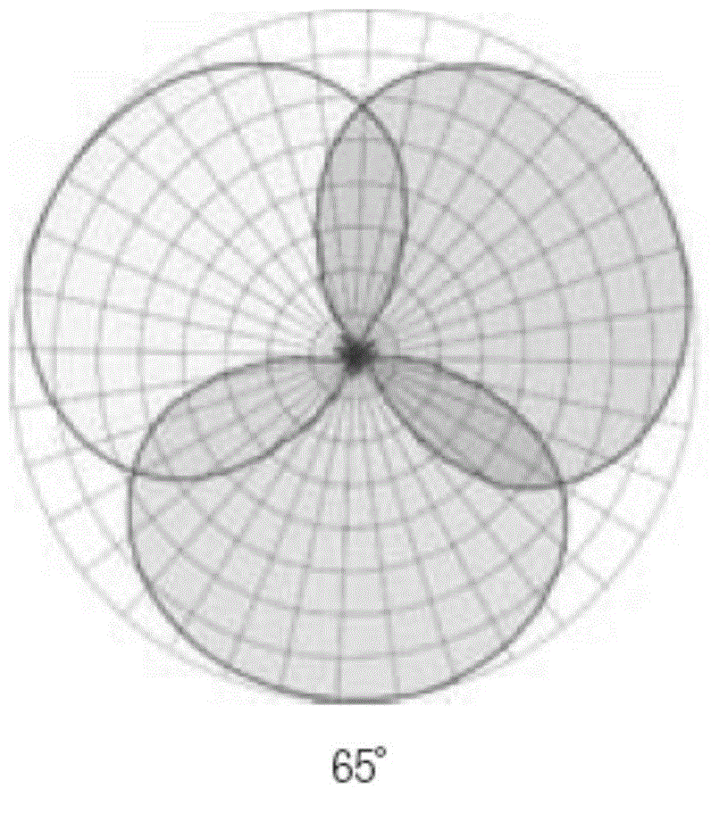
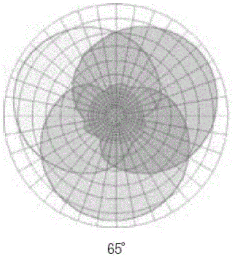
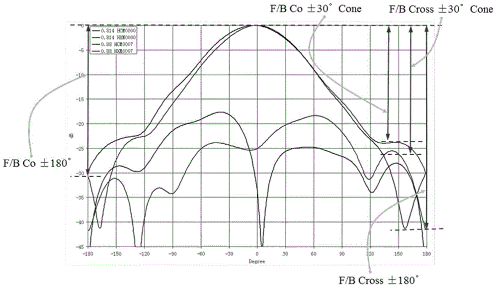
[0004] In order to improve the front-to-back ratio of the directional base station antenna, one method is to increase the metal reflector of the base station antenna, but excessively increasing the size of the reflector not only wastes materials, but also increases the space occupied by the base station antenna, and also increases the Difficulty in processing reflectors
Another method is to place a backplane behind the backplane of the base station antenna. Usually, the shape and size of the backplane and the bottom plate are the same. Such a backplane cannot effectively suppress the backward radiation wave of the antenna, especially for directional array antennas.

Method used


Image

  • Backboard of base station antenna and base station antenna
  • Backboard of base station antenna and base station antenna
  • Backboard of base station antenna and base station antenna

Examples


Embodiment Construction

[0028] In the following detailed description of the preferred embodiment, reference is made to the accompanying drawings which form a part hereof. The accompanying drawings show, by way of example, specific embodiments in which the invention can be practiced. The illustrated embodiments are not intended to be exhaustive of all embodiments in accordance with the invention. It should be noted that although the steps of the relevant methods in the present invention are described in a specific order in the accompanying drawings, this does not require or imply that these operations must be performed in this specific order, or that all shown operations must be performed to achieve the desired result. As a result, instead, the steps described herein can be performed in a different order. Additionally or alternatively, certain steps may be omitted, multiple steps may be combined into one step for execution, and / or one step may be decomposed into multiple steps for execution.

[0029...


PUM


Abstract

The invention relates to a backboard of a base station antenna. The backboard comprises a backboard bottom surface and backboard side plates. The backboard bottom surface is arranged below a bottom plate in parallel. The middle parts of two sides of the backboard bottom surface are respectively provided with one backboard side plate. Each backboard side plate is bent in an L shape. One side, bent in the L shape, of each backboard side plate is connected with the backboard bottom surface, the other side of each backboard side plate faces a radiation unit, and each backboard side plate does not contact the bottom plate. The base station antenna adopting the backboard further comprises the bottom plate. The bottom plate is arranged above the backboard in parallel without contact. Two sides, arranged in the same directions of the L-shaped bent backboard side plates, of the bottom plate are bent upwards. The base station antenna also comprises the radiation unit which is arranged on the middle part of the bottom plate. By adopting the scheme provided by the invention, the size of the base station antenna is reduced, and compared with an existing backboard, a front-to-back ratio is increased by 3 to 5 dB; in addition, the backboard is easy to machine and installed, readjustment is not needed in large-scale production.

Description

technical field [0001] The present invention generally relates to the field of mobile communication, and in particular relates to a base station antenna backplane and a base station antenna. Background technique [0002] With the development of mobile communication networks, the application environment of base station antennas becomes more and more complex. The requirements for network planning and optimization are also becoming higher and higher. Especially in cities, the cellular network is very dense, and the selection of site is becoming more and more difficult. Shared sites lead to more and more antennas installed on the same site. For the antennas on these sites, it is necessary to Antennas with a better front-to-back ratio are needed to solve the interference problem between antennas. For antennas at adjacent sites in cities, antennas with a better front-to-back ratio are also needed to solve the problems of handover confusion and call drop caused by cross-area cover...

Claims


Application Information

Patent Timeline
Patent Type & Authority Applications(China)
IPC IPC(8): H01Q15/14
Inventor 徐澄宇
Owner 安弗施技术公司
Learn More