A Small Circularly Polarized GPS-BD Microstrip Antenna with Positioning Capability

A GPS-BD, positioning capability technology, applied in antennas, resonant antennas, electrical short antennas, etc., can solve the problems of increasing the height of the antenna profile and affecting the practicability of the antenna, achieving good circular polarization characteristics and improving the effect of the front-to-back ratio

Active Publication Date: 2021-12-14
XIDIAN UNIV
View PDF17 Cites 0 Cited by
  • Summary
  • Abstract
  • Description
  • Claims
  • Application Information

AI Technical Summary

Problems solved by technology

In order to ensure a 180-degree phase difference, the reflector usually needs to be placed at a quarter wavelength below the radiator, which greatly increases the antenna's profile height, thereby affecting the practicability of the antenna

Method used


Image

  • A Small Circularly Polarized GPS-BD Microstrip Antenna with Positioning Capability
  • A Small Circularly Polarized GPS-BD Microstrip Antenna with Positioning Capability
  • A Small Circularly Polarized GPS-BD Microstrip Antenna with Positioning Capability

Examples


Embodiment 1

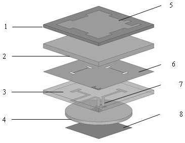
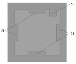
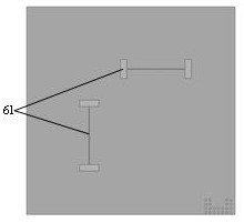
[0034] like figure 1 As shown, a small circularly-polarized GPS-BD microstrip antenna having a positioning ability, comprising a first dielectric substrate 1, a second dielectric substrate 2, a third dielectric substrate 3, a first dielectric substrate 2, a second dielectric substrate 2, a third dielectric substrate 3 And the fourth dielectric substrate 4; the first dielectric substrate 1 is located at the top layer, and the upper layer radiating unit 5 is printed on the upper surface of the first dielectric substrate 1; the second dielectric substrate 2 is close to the first dielectric substrate 1; The third dielectric substrate 3 is in close to the second dielectric substrate 2, and the metal floor 6 is printed on the upper surface of the third dielectric substrate 3, and the second medium substrate 3 is printed is printed with the feed network 7; the fourth medium The substrate 4 is close to the third dielectric substrate 3, and the lower surface radiation unit 8 is printed in ...

Embodiment 2

[0046] The structure of the present embodiment is the same as that of the first embodiment, and the following parameters are adjusted:

[0047] The upper radiation unit 5 side length L = 38 mm, the lower radiation unit edge length D = 30.3 mm, the diameter φ of the fourth dielectric substrate is 44 mm, the metal floor is square, and the size is 50 mm × 50 mm. The metal material employed in this example is specifically copper.

[0048] The following combination of simulation experiments is further illustrated by the technical effects of the present invention:

[0049] 1, simulation conditions and content:

[0050] 1.1 reference figure 1 The antenna includes the first dielectric substrate 1, the second dielectric substrate 2, the third dielectric substrate 3, and the fourth dielectric substrate 4, the upper radiation unit 5, the metal floor 6, the feed network 7, the lower radioscope unit 8, The upper radiation unit 5 is printed on the upper surface of the first dielectric substrate...


PUM

PropertyMeasurementUnit
thicknessaaaaaaaaaa
thicknessaaaaaaaaaa
thicknessaaaaaaaaaa

Abstract

The invention belongs to the field of antenna technology, and relates to a small circularly polarized GPS-BD microstrip antenna with positioning capability, which is characterized in that it includes a first dielectric substrate, a second dielectric substrate, a third dielectric substrate, and a third dielectric substrate that are stacked up and down and whose geometric centers overlap each other. a dielectric substrate and a fourth dielectric substrate; the first dielectric substrate is located on the uppermost layer, and the upper surface of the first dielectric substrate is printed with an upper radiation unit; the second dielectric substrate is closely attached to the bottom of the first dielectric substrate; the third The dielectric substrate is closely attached to the bottom of the second dielectric substrate, the upper surface of the third dielectric substrate is printed with a metal floor, and the lower layer of the third dielectric substrate is printed with a feeding network; the fourth dielectric substrate is closely attached to the bottom of the third dielectric substrate, The lower radiation unit is printed on the lower surface of the fourth dielectric substrate. It aims to realize the miniaturization of the microstrip antenna under the premise of ensuring the normal radiation of the antenna.

Description

Technical field [0001] The present invention belongs to the field of antenna technology, which relates to a small circularly-polarized GPS-BD microstrip antenna having positioning ability, and can be used in a variety of locations with positioning requirements. Background technique [0002] In the current navigation positioning system, the antenna as the core part, in addition to the requirements of the circularly polarization, with the miniaturization of various radio components, the development of spatial technology, and people's requirements for narrowing antenna size are more urgent. [0003] The microstrip antenna is on a thin dielectric substrate, and the metal thin layer is attached as a ground plate, and the other side is etched for a certain shape of a metal patch, using a microstrip line or a coaxial probe to feed the patch feed. Because it has the advantages of small size, light weight, simple manufacturing process, easy conformity, and is widely used. [0004] Specifi...

Claims


Application Information

Patent Timeline
Patent Type & Authority Patents(China)
IPC IPC(8): H01Q1/38H01Q9/04
CPCH01Q1/38H01Q9/0414H01Q9/0428H01Q9/045
Inventor 史琰张璇王花杰
Owner XIDIAN UNIV
Why Eureka
Try Eureka