
display screen

A display device and substrate technology, applied in the direction of optics, instruments, electrical components, etc., can solve the problems that the display area of ​​the display panel cannot be displayed, cannot meet user requirements, display, etc.

Active Publication Date: 2018-08-10
INNOLUX CORP
View PDF13 Cites 0 Cited by
  • Summary
  • Abstract
  • Description
  • Claims
  • Application Information

AI Technical Summary

Problems solved by technology

[0004] However, in the display panel of a general display device, even if the substrate is cut with an arc-shaped edge by using a special-shaped cutting method, the display area of ​​the display panel cannot present a perfect circle, ellipse or other circle-like shape due to the setting of the drive unit. Graphical display, but can not meet the user's requirements

Method used


Image

  • display screen
  • display screen
  • display screen

Examples


Embodiment Construction

[0034] The implementation of the present invention is illustrated by specific specific examples below, and those skilled in the art can easily understand other advantages and effects of the present invention from the content disclosed in this specification. The present invention can also be implemented or applied by other different specific embodiments, and various modifications and changes can be made to the details in this specification for different viewpoints and applications without departing from the spirit of the present invention.

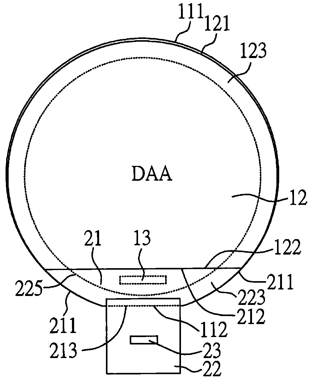
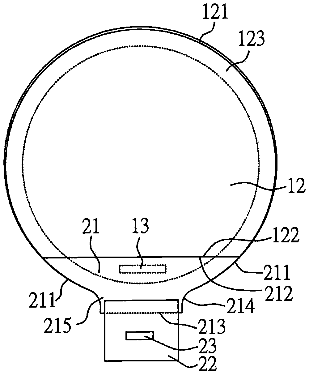
[0035] Figure 1A and figure 2 It is a plan view and a schematic cross-sectional view of a quasi-circular display device according to a preferred embodiment of the present invention.

[0036] Such as Figure 1A and figure 2 As shown, in the structure of the display device and its manufacturing method in this embodiment, first, a first substrate 11 is provided, which is a substrate with a special-shaped structure through special-shaped cu...


PUM

PropertyMeasurementUnit
thicknessaaaaaaaaaa

Abstract

The invention discloses display equipment, which comprises a display panel and a making-up panel, wherein the display panel comprises a first substrate, a second substrate, a driving unit and the making-up panel; the second substrate is opposite to the first substrate and partially covers the first substrate, and the second substrate comprises a second arc-shaped edge and a second side; the second arc-shaped edge and the second side are connected; the driving unit is arranged on the part, not covered by the second substrate, of the first substrate; the making-up panel is arranged on the driving unit and comprises a third arc-shaped edge and a third side; the third arc-shaped edge and the third side are connected, wherein the third side and the second side mutually correspond; and the third arc-shaped edge and the second arc-shaped edge mutually corresponds.

Description

technical field [0001] The present invention relates to a display device, in particular to a display device with a display area approaching a circle. Background technique [0002] With the continuous advancement of display technology, all devices are developing toward small size, thin thickness, and light weight. Therefore, the current mainstream display devices on the market have developed from the previous cathode ray tubes to thin display devices, such as liquid crystal display devices. and organic light emitting diode devices. In particular, thin display devices can be applied in many fields, such as watches, mobile phones, notebook computers, video cameras, cameras, music players, mobile navigation devices, televisions and other display devices used in daily life. [0003] In the past, most common display devices had a square structure; in recent years, in order to meet the needs of aesthetics and design, they have been designed to have various shapes, such as circular...

Claims


Application Information

Patent Timeline
Patent Type & Authority Patents(China)
IPC IPC(8): G09F9/00G09F9/30G02F1/1333H01L27/32
Inventor 吴政珉施建丰黄圣峰
Owner INNOLUX CORP
Learn More