
Polygon object change detection method and device

A change detection and polygon technology, applied in the field of high-resolution remote sensing, can solve the problems that affect the efficiency and accuracy of change detection, poor effect, and prominent projection difference.

Active Publication Date: 2016-06-01
SPACE STAR TECH CO LTD
View PDF4 Cites 7 Cited by
  • Summary
  • Abstract
  • Description
  • Claims
  • Application Information

AI Technical Summary

Problems solved by technology

[0006] The above-mentioned method of applying remote sensing data to update GIS data mainly has the following problems at present: (1) the above-mentioned method is to first extract the target in the image by classification, and then perform change detection, and the target recognition algorithm is very complicated, and the effect is poor, seriously affecting The efficiency and accuracy of change detection are improved; (2) In high-resolution images, the projection difference caused by non-orthographic is more prominent, so the traditional image registration is aimed at the whole image, but has a large deviation for the target individual; (3 ) only considers the intensity of the target edge and ignores the changes around the target, which has poor versatility

Method used


Image

  • Polygon object change detection method and device
  • Polygon object change detection method and device
  • Polygon object change detection method and device

Examples


Embodiment 1

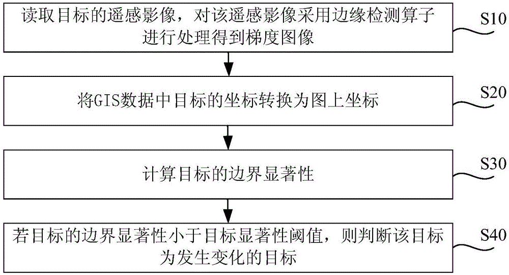
[0083] Such as figure 1 Shown is a flow chart of the change detection method for a polygonal target provided by an embodiment of the present invention. In this embodiment, GIS polygonal data is used as the target (wherein the GIS data is marked with the outline of the target, which is the historical data of the target), Use high-resolution remote sensing images for change detection (the high-resolution remote sensing images are the update data of the target, and the remote sensing image data after the target changes). For example, take the GIS data of a house in a certain place as the target, the data format is shapefile, and the high-resolution remote sensing image after the earthquake in the area where the house is located, the resolution is meter level, and the data format is geotiff.

[0084] The change detection method of the house target includes the following steps:

[0085] Step S10 , read the remote sensing image img0 of the target, and process the remote sensing ima...

Embodiment 2

[0124] Such as Figure 6 As shown, it is a block diagram of a change detection device for a polygonal object provided by an embodiment of the present invention. In combination with the method in Embodiment 1, the device 100 includes: an image processing module 10, a coordinate conversion module 20, and a buffer construction module 30, A pixel point set extraction module 40 , a gradient set extraction module 50 , a calculation module 60 and a judgment module 70 .

[0125] Wherein, the image processing module 10 is used to read the remote sensing image of the target, and uses the sobel operator, Roberts operator or Laplacian operator to process the remote sensing image to obtain a gradient image; the coordinate conversion module 20 is used to The latitude and longitude coordinates of the GIS data of the target are converted into geographic coordinates according to the geodetic coordinate system, and then the geographic coordinates are converted into coordinates on the map accord...


PUM


Abstract

The invention discloses a polygon object change detection method and device. The method comprises following steps: under a coordinate of a map of the object, a boundary buffer area and an integral buffer area of the object are constructed on the basis of GIS data of the object; a pixel point set of the boundary buffer area and a pixel point set of the non-boundary of the integral buffer area are extracted; a boundary point gradient set of the boundary buffer area and a non-boundary point gradient set of the integral buffer area are extracted from a gradient image of the object on the basis of the extracted pixel point sets; a boundary significance value of the object is calculated by use of a z value test method on the basis of the extracted gradient sets; and if the calculated boundary significance value is less than a set boundary significance threshold value, the object is determined as changed. The provided method and device are simple and have high efficiency, high detection precision, high accuracy, and high automation degree.

Description

technical field [0001] The invention relates to the technical field of high-resolution remote sensing, in particular to a method and device for detecting changes in polygonal targets. Background technique [0002] With the construction of smart cities and digital earth, my country has built a large number of basic and thematic spatial data sets, which play an important role in various industries such as land and resources survey, urban planning, disaster forecast and damage assessment. Remote sensing satellite observation has the characteristics of short time period and wide observation range, and can easily obtain continuous time series data in a large spatial range. Therefore, using remote sensing data to detect and update spatial datasets has important practical significance and broad application prospects. [0003] Remote sensing change detection technology originated in the 1960s, and the main directions of current research are focused on the use of multi-temporal remo...

Claims


Application Information

Patent Timeline
IPC IPC(8): G06T7/00
Inventor 刘明超李翔翔汪红强王剑
Owner SPACE STAR TECH CO LTD
Learn More