
Flexible liquid crystal display panel and display device

A flexible liquid crystal display and panel technology, which is applied in nonlinear optics, instruments, optics, etc., can solve the problems of light leakage and non-perpendicularity of flexible liquid crystal display panels, and achieve the effect of improving the problem of dark state light leakage.

Active Publication Date: 2016-06-01
BOE TECH GRP CO LTD
View PDF5 Cites 2 Cited by
  • Summary
  • Abstract
  • Description
  • Claims
  • Application Information

AI Technical Summary

Problems solved by technology

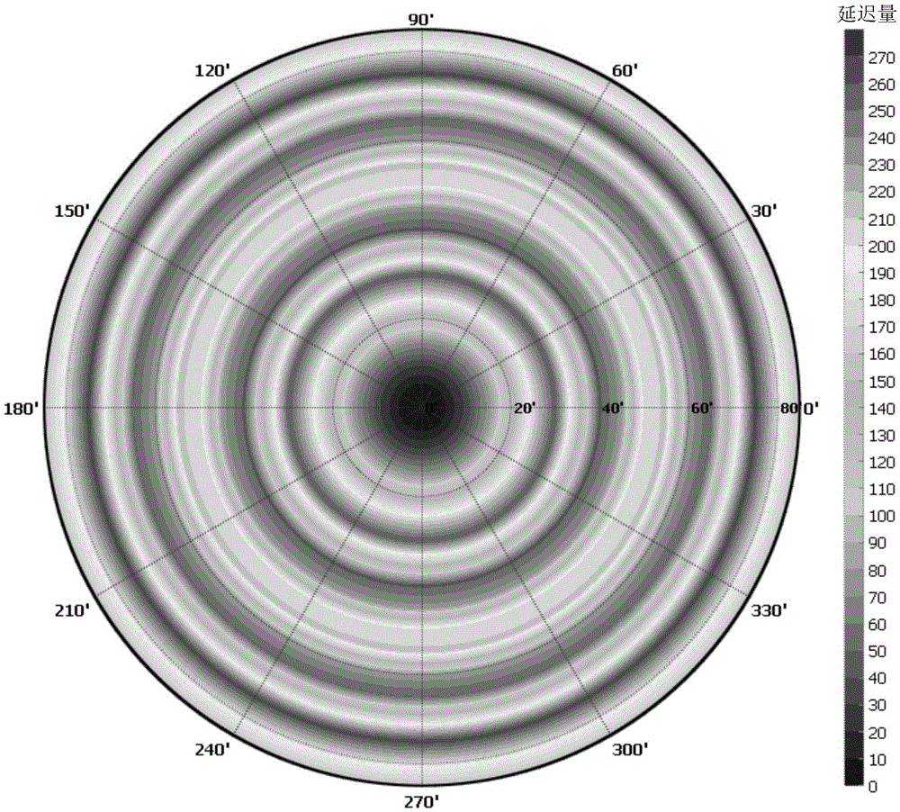
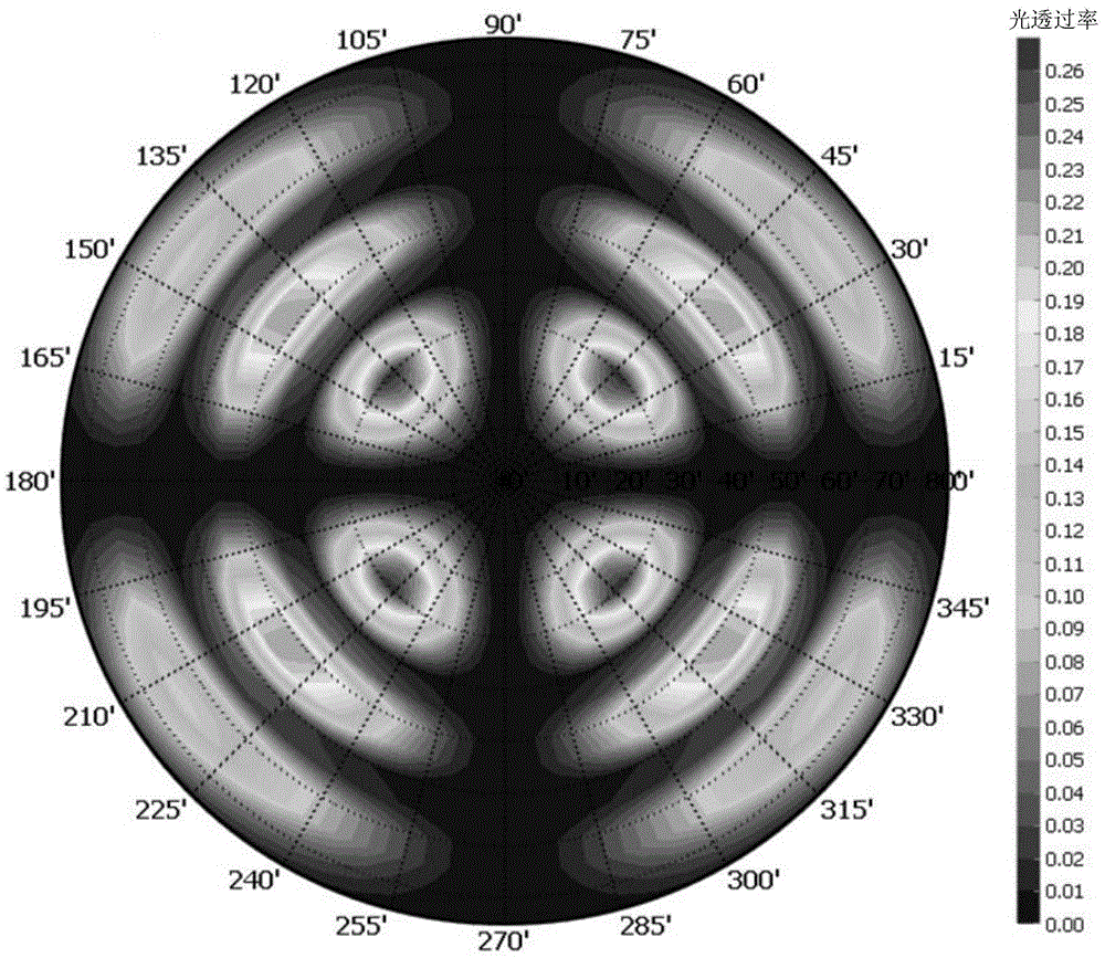
[0005] And, according to the angle formula of the absorption axes of the upper and lower polarizers of the flexible liquid crystal display panel, Among them, ψ is the angle between the absorption axes of the upper and lower polarizers, φ 1 and φ 2 are the azimuth angles of the upper and lower polarizers when the viewing angle is zero, φ k is the azimuth angle of the human eye when the viewing angle is greater than zero, θ k is the polar angle of the human eye when the viewing angle is greater than zero; when the viewing angle is greater than zero, the angle between the light absorption axes of the upper and lower polarizers of the flexible liquid crystal display panel is not vertical, which will also cause the light leakage problem of the flexible liquid crystal display panel in the dark state

Method used


Image

  • Flexible liquid crystal display panel and display device
  • Flexible liquid crystal display panel and display device
  • Flexible liquid crystal display panel and display device

Examples


example 1

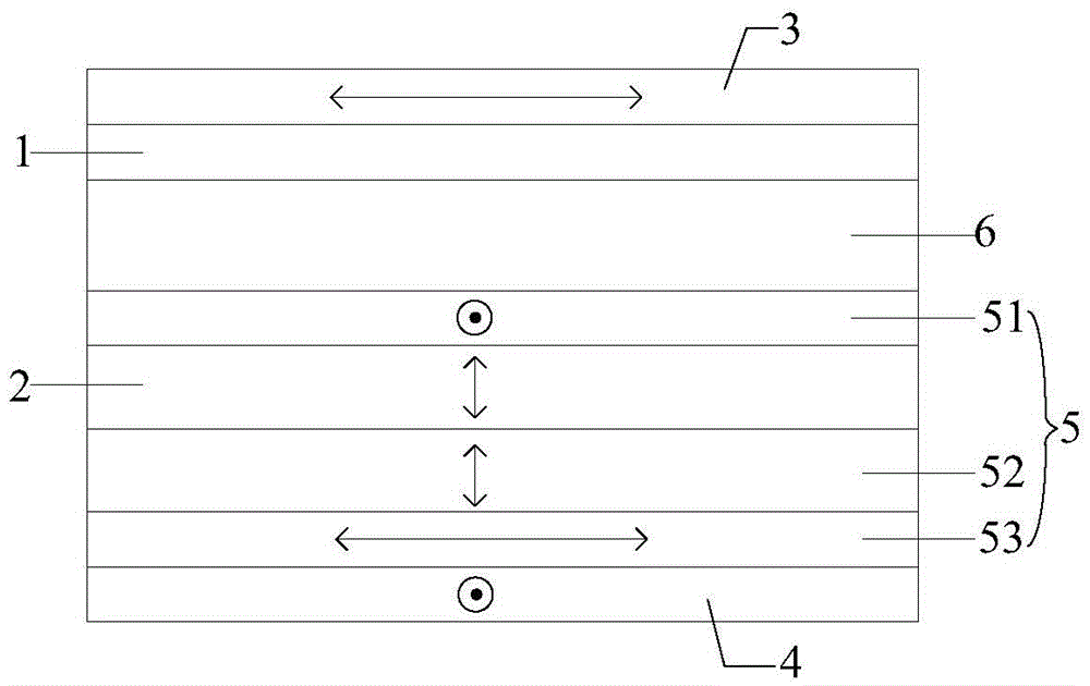
[0055] Example 1: If Figure 3a As shown, the compensation film 5 includes: a first compensation film 51 located between the second flexible substrate 2 and the liquid crystal cell 6, and a second flexible substrate 2 located between the second polarizer 4 and on the second flexible substrate 2 The second compensation film 52 and the third compensation film 53 are sequentially stacked on the top; wherein, the optical axis of the first compensation film 51 and the light absorption axis of the second polarizer 4 are parallel to each other, which is equivalent to an -Aplate; the first compensation film 51 The range of the retardation Ro of the plane where the second compensation film 52 is located is -80nm to -100nm; the optical axis of the second compensation film 52 is perpendicular to the second flexible substrate 2, which is equivalent to a +Cplate; the retardation of the plane where the second compensation film 52 is located The range of Ro is 2320nm to 2380nm; the optical a...

example 2

[0063] Example 2: If Figure 4a As shown, the compensation film 5 includes: a first compensation film 51 and a second compensation film 52 that are sequentially stacked between the second flexible substrate 2 and the second polarizer 4 and arranged on the second flexible substrate 2; The optical axis of a compensation film 51 is perpendicular to the second flexible substrate 2, which is equivalent to a +Cplate; the retardation Ro of the plane where the first compensation film 51 is located ranges from 2360nm to 2440nm; the optical axis of the second compensation film 52 and The light absorption axes of the first polarizer 3 are parallel to each other, corresponding to an -Aplate; the retardation Ro of the plane where the second compensation film 52 is located ranges from -120nm to -150nm. It should be noted that the optical axis of the second flexible substrate 2 is perpendicular to its surface, and the retardation of its plane is Ro=0nm.

[0064] In specific implementation, ...

example 3

[0070] Example 3: If Figure 5a As shown, the compensation film 5 includes: a first compensation film 51 and a second compensation film 52 that are sequentially stacked between the second flexible substrate 2 and the liquid crystal cell 6 and arranged on the second flexible substrate 2; wherein, the first compensation film The optical axis of the film 51 is perpendicular to the second flexible substrate 2, which is equivalent to a +Cplate; the retardation Ro of the plane where the first compensation film 51 is located ranges from 2400nm to 2450nm; the optical axis of the second compensation film 52 and the second The light absorption axes of the polarizers 4 are parallel to each other, corresponding to an -Aplate; the retardation Ro of the plane where the second compensation film 52 is located ranges from -120nm to -160nm. It should be noted that the optical axis of the second flexible substrate 2 is perpendicular to its surface, and the retardation of its plane is Ro=0nm.

...


PUM

PropertyMeasurementUnit
Amount of delayaaaaaaaaaa

Abstract

The invention discloses a flexible liquid crystal display panel and a display device. The flexible liquid crystal display panel comprises a first flexible substrate, a second flexible substrate, a first polarizer and a second polarizer, wherein the first flexible substrate and the second flexible substrate are oppositely arranged; the first polarizer and the second polarizer are positioned outside the two flexible substrates; the second flexible substrate is made of organic resin; due to addition of a compensation film between the first polarizer and the second polarizer, the compensation film can compensate a phenomenon of dark-state light leakage generated due to a retardation of the second flexible substrate and an included angle of greater or smaller than 90 degrees between a light adsorption axis of the first polarizer and a light adsorption axis of the second polarizer, so that the problem of dark-state light leakage caused by the retardation of the second flexible substrate and the case that the light adsorption axis of the first polarizer is not perpendicular to the light adsorption axis of the second polarizer when a view angle is greater than zero can be improved.

Description

technical field [0001] The invention relates to the field of display technology, in particular to a flexible liquid crystal display panel and a display device. Background technique [0002] With the rapid development of display technology, flexible display panels have the advantages of thin and light weight, drop resistance, bendability, power saving and energy saving, etc. Liquid crystal display panels (LCD, Liquid Crystal Display) have low power consumption, high display quality, no electromagnetic radiation and application The advantages of wide range make the flexible liquid crystal display panel become a research hotspot in the field of display. [0003] Existing flexible liquid crystal display panels generally use polyimide (PI) film as a flexible substrate. This is because the PI film can withstand a high temperature close to 400°C. Damaged due to the high temperature environment when forming the active layer in the thin film transistor. [0004] When the flexible l...

Claims


Application Information

Patent Timeline
IPC IPC(8): G02F1/1333G02F1/13363G02F1/1335
CPCG02F1/133305G02F1/133528G02F1/13363G02F1/133531G02F2202/40G02F2413/03G02F2413/07G02F2413/13G02F2413/14G02F1/133634G02F1/134363G02F2201/121G02F2201/123
Inventor 贾倩王英涛赵伟利
Owner BOE TECH GRP CO LTD
Learn More