
Radiation source positioning method based on receiving signal power information

A technology for receiving signal power and receiving signals, which is applied in the research and application field of electromagnetic spectrum monitoring technology, and can solve problems such as bulky volume, limited application, and impact of positioning results.

Active Publication Date: 2016-06-01
WUHAN RUITIAN BOPU INFORMATION TECH CO LTD
View PDF7 Cites 7 Cited by
  • Summary
  • Abstract
  • Description
  • Claims
  • Application Information

AI Technical Summary

Problems solved by technology

[0003] If the radiation source positioning method of measuring the incoming direction of electromagnetic waves is used, due to the complex geographical environment of the city and the multipath effect caused by the non-line-of-sight propagation of radio waves, it will have a great impact and uncertainty on the positioning results
In addition, the technology of direction finding equipment is complex, bulky and expensive
If the method of measuring the absolute time of the arrival of electromagnetic waves at multiple detection terminals is used to locate the radiation source, it is required that the clocks of each detection terminal must be synchronized with the clock of the radiation source with high precision, which is impossible when locating non-writing radiation sources However, the application of this method is completely limited; if the radiation source positioning is completed by the time difference between the arrival of electromagnetic waves at multiple detection terminals, in addition to requiring that the detection terminals must maintain clock synchronization, the geometric position of the detection terminal and its relationship with the radiation source The distance and other factors also seriously affect the positioning accuracy and spatial resolution

Method used


Image

  • Radiation source positioning method based on receiving signal power information
  • Radiation source positioning method based on receiving signal power information
  • Radiation source positioning method based on receiving signal power information

Examples


Embodiment Construction

[0079] The specific implementation will be further described below in conjunction with the accompanying drawings and the content of the present invention.

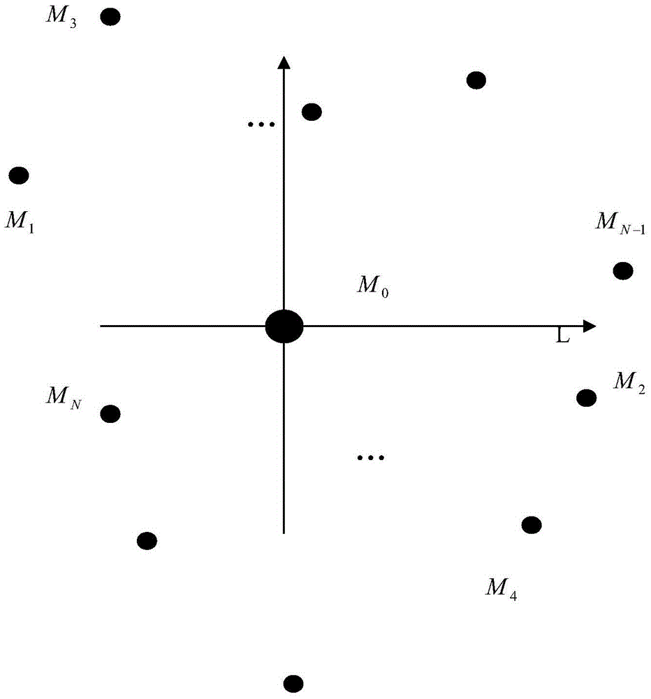
[0080] Such as figure 1 As shown, in the electromagnetic spectrum monitoring system composed of multiple detection terminals and a central station, the method for locating the radiation source is implemented, and the specific steps include:

[0081] 1. First, specify the frequency range and time period of the received signal. The reception time period is from the start moment to the end moment. If the detection receiver (hereinafter referred to as the detection terminal) receives the The signal power spectrum information of the signal, the detection terminal is included in the detection terminal set to be used;

[0082] 2. Determine the detection terminals that can be used for positioning in the concentration of detection terminals to be used

[0083] by figure 2 The relative position of each detection terminal shown i...


PUM


Abstract

The invention provides a radiation source positioning method based on receiving signal power information. The radiation source positioning method comprises the steps that a standby detection terminal set is selected; detection terminals used for positioning calculation are selected; signal power received by all the detection terminals within the designated frequency range and time period are calculated; rough positioning is performed by utilizing the position coordinates of all the detection terminals and the received electromagnetic power; and positioning is performed again by utilizing the rough positioning result so that an accurate positioning result is obtained. Positioning of a radiation source is enabled to be more accurate and reliable by two times of positioning; and a local ground rectangular coordinate system is adopted in transformation of the position coordinates of all the detection terminals so that the problem that large error is possibly generated in transformation of geodetic coordinates to geocentric rectangular coordinates can be avoided.

Description

technical field [0001] The invention belongs to the field of electromagnetic spectrum monitoring technology research and application, relates to radiation source positioning technology, and in particular to a radiation source positioning method based on received signal power information. Background technique [0002] With the continuous utilization of radio spectrum resources, spectrum resources are becoming increasingly crowded. Therefore, it is necessary to effectively monitor the use of regional spectrum. One of the key indicators is to obtain the location information of radiation sources in real time or quasi-real time. At present, the radiation source location methods mainly include: (1) Obtain the azimuth line of the radiation source by measuring the incoming direction of the electromagnetic wave, and then perform cross-location through the azimuth lines measured by multiple stations; (2) Measure the electromagnetic signal to reach multiple detection terminals Radiatio...

Claims


Application Information

Patent Timeline
IPC IPC(8): G01S5/02
CPCG01S5/02
Inventor 马洪庞淑萍
Owner WUHAN RUITIAN BOPU INFORMATION TECH CO LTD
Learn More