
Performance testing device of automobile clutch system

A test device, clutch technology, applied in the direction of machine gear/transmission mechanism test, etc., can solve the problem of not getting the pedal force relationship curve, the preparation work of the vehicle performance test is complicated, time-consuming and labor-intensive, etc.

Active Publication Date: 2016-06-01
GUANGZHOU AUTOMOBILE GROUP CO LTD
View PDF11 Cites 15 Cited by
  • Summary
  • Abstract
  • Description
  • Claims
  • Application Information

AI Technical Summary

Problems solved by technology

Although the performance parameters of the pedal and the clutch can be accurately measured by using the existing method, the relationship curve between the pedal force, the pedal stroke and the separation force and the separation stroke cannot be obtained, and, due to the clearance of the operating mechanism and the problem of transmission efficiency, the clutch pair Existing methods cannot test how the driver responds to actions
In addition, since the clutch is installed in the gearbox casing, the gearbox needs to be removed to install the sensor and holes are drilled in the casing during the test, which makes the preparation for the vehicle performance test complicated, time-consuming and laborious

Method used


Image

  • Performance testing device of automobile clutch system
  • Performance testing device of automobile clutch system
  • Performance testing device of automobile clutch system

Examples


Embodiment Construction

[0024] In order to further explain the technical means and effects adopted by the present invention to achieve the intended invention purpose, the specific implementation, structure, features and effects of the present invention will be described in detail below in conjunction with the accompanying drawings and preferred embodiments.

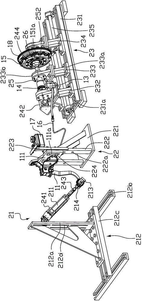
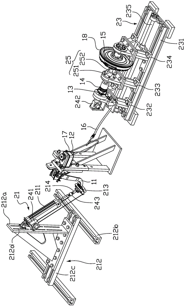
[0025] Such as Figure 1 to Figure 4 As shown, the performance testing device of the automobile clutch system of the present invention is used to detect the clutch system of the automobile, and the automobile clutch system includes a clutch pedal 11, a clutch master cylinder 12, a clutch slave cylinder 13, a release bearing 14, a clutch 15 and a flywheel 18. The clutch master cylinder 12 and the clutch slave cylinder 13 are connected through a pipeline 16. The performance testing device of the present invention includes a clutch pedal loading system 21, a clutch pedal mounting frame 22, a mounting stand 23, a linear bearing 25, and a plurality o...


PUM


Abstract

Disclosed is a performance testing device of an automobile clutch system. The automobile clutch system comprises a clutch pedal, a clutch master cylinder, a clutch slave cylinder, a release bearing, a clutch and a flywheel. The performance testing device comprises a clutch pedal loading system, a clutch pedal mounting rack, an installation bench, a linear bearing and a plurality of sensors. The clutch pedal is installed on the clutch pedal mounting rack. The installation bench comprises a base, a release bearing mounting rack, a linear bearing mounting rack and a flywheel mounting rack. The release bearing mounting rack, the linear bearing mounting rack and the flywheel mounting rack are successively arranged along the base. The release bearing mounting rack is disposed near the clutch pedal mounting rack. The sensors comprise a first force sensor for detecting a pedal force of the clutch pedal, a first displacement sensor for detecting a pedal stroke of the clutch pedal, a second force sensor for detecting a separating force of the clutch, and a second displacement sensor for detecting a separating stroke of the clutch.

Description

technical field [0001] The invention relates to the technical field of automobile inspection, in particular to a performance test device for an automobile clutch system. Background technique [0002] The clutch is located between the engine and the gearbox, and the output shaft of the clutch is the input shaft of the gearbox. When the car is running, the driver can step on or release the clutch pedal as needed to separate the driven disc of the clutch from the flywheel of the engine or Engage, so that the engine and the gearbox are temporarily separated or gradually engaged, so as to cut off or transmit the power input from the engine to the gearbox, and play the role of cutting and connecting the engine power, so as to ensure the car starts and shifts smoothly, and can also prevent transmission The system is overloaded, transmitting torque. Usually, the separation force of the clutch is 1000N or even higher. According to ergonomic requirements, the pedal force of a car is ...

Claims


Application Information

Patent Timeline
IPC IPC(8): G01M13/02
Inventor 李涛吴孝曦董川川
Owner GUANGZHOU AUTOMOBILE GROUP CO LTD
Learn More