Eureka AIR delivers breakthrough ideas for toughest innovation challenges, trusted by R&D personnel around the world.

Tower crane attachment device

A technology for attachment devices and tower cranes, which is applied to cranes and other directions, can solve problems such as tower crane overturning safety accidents, breakage, tower crane overturning, etc., and achieve the effect of overcoming installation difficulties

Pending Publication Date: 2019-03-29
安顺中安安装工程有限公司
View PDF15 Cites 7 Cited by
  • Summary
  • Abstract
  • Description
  • Claims
  • Application Information

AI Technical Summary

Problems solved by technology

Both ends must be set on the same level, otherwise the connecting pin cannot be inserted into the pin hole, resulting in great difficulty in installation and disassembly
The reasons why the two ends cannot be set on the same level are as follows: first, the manual installation by the operator cannot ensure that the two ends are on the same plane; There are crawling claws that need to avoid these places to set up attachments
Therefore, many existing solutions are to use electric welding to connect the parts in the attachment device, but the strength of the electric welding connection is not as good as the pin connection, so once there is a problem in the welding, it will lead to a series of major safety accidents such as adhesion fracture and tower crane overturning.
[0003] In addition, in the existing tower crane attachment, the frame attached to the tower crane is in direct contact with the standard section of the tower crane. The force bearing surface of the tower crane is extremely small, the impact force on the force surface is extremely large, and the friction force is also extremely large. The four columns of the standard section bear The impact force and shear force are not uniform, and the attachment device cannot play the role of stabilizing the tower crane and buffering the release force
Therefore, the standard section of the tower crane is easily deformed, bent, and broken, resulting in major safety accidents caused by the overturning of the tower crane.
[0004] Secondly, the frame of the existing tower crane attachment device is a fixed structure, which can only be applied to the standard section of the corresponding specification.

Method used


Image

  • Tower crane attachment device
  • Tower crane attachment device
  • Tower crane attachment device

Examples


Embodiment 1

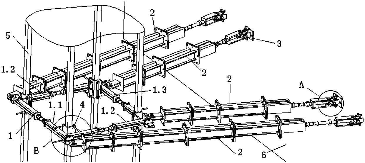
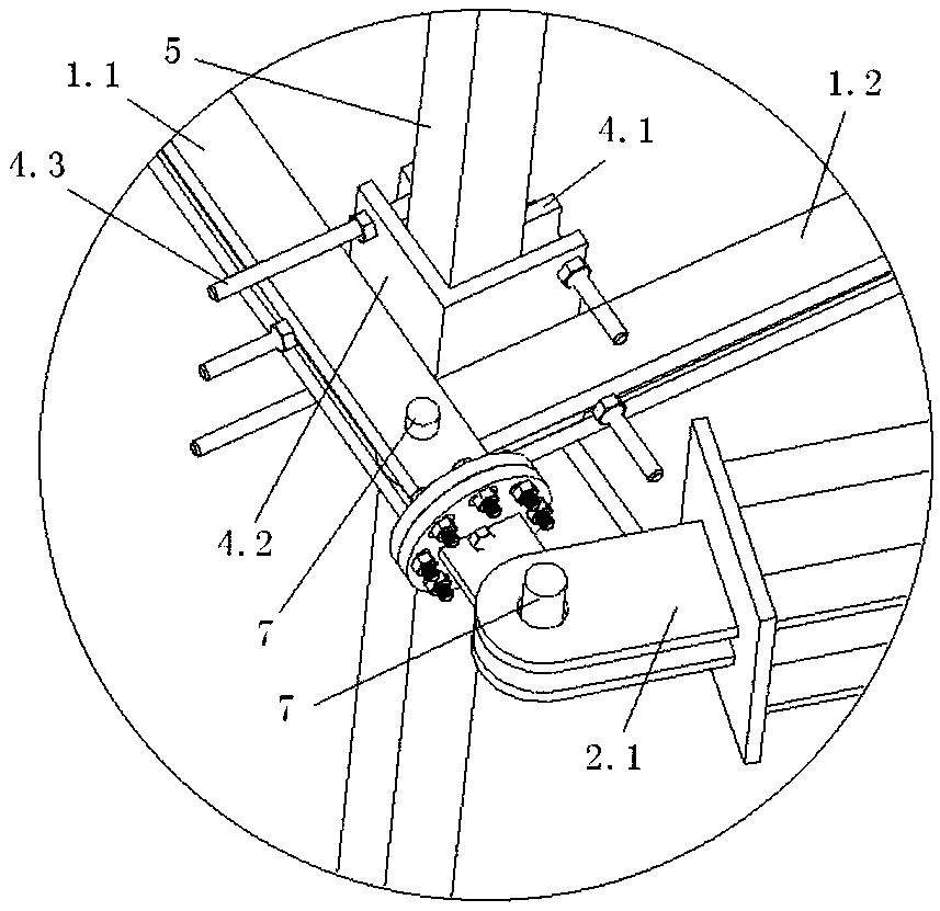
[0050] see Figure 1-11 , a tower crane attachment device, including an attachment frame 1, an adjustable support unit 2 and an adjustable fixing seat 3; the attachment frame is arranged on the tower crane standard section 5, and the adjustable fixing seat 3 is arranged on the fixing surface 6 of the attachment device , the adjustable support single piece connects the attachment frame and the adjustable fixing seat; the installation angle between the attachment frame and the adjustable fixing seat can be adjusted through the cooperation of the attachment frame, the adjustable support single piece and the adjustable fixing seat.

[0051] see figure 2 , the adjustable fixed seat 3 includes a fixed bottom plate 3.1, a rotating base 3.2 and a pin shaft 7 arranged on the fixing surface 6 of the attachment device, and the fixed bottom plate 3.1 and the rotating base 3.2 are provided with a pin shaft for installing the pin shaft 7 hole, the rotating base 3.2 is rotatably connected ...


PUM


Abstract

The invention provides a tower crane attachment device. The device includes an attachment frame, adjustable support single pieces and adjustable fixing bases. The attachment frame is arranged on a tower crane standard section. The adjustable fixing bases are arranged on an attachment device fixing plane. The adjustable support single pieces connect the attachment frame and the adjustable fixing bases. The mounting angles between the attachment and the adjustable fixing bases are adjustable through the cooperation of the attachment frame, adjustable support single pieces and adjustable fixing bases. The attachment device of the invention effectively solves the problem that an attachment frame on a tower crane and fixing points on a building are not in the same plane in the prior art. The problem that the standard section is prone to deformation, bending and breaking due to small stress surface of the tower crane caused by the direct contact between the attachment frame and the tower crane standard section in the prior art is improved through the arrangement of guard plate groups. The attachment device of the invention can be universally applied to standard sections of different specifications by arranging the size of the attachment frame to be adjustable.

Description

technical field [0001] The invention relates to the technical field of tower cranes, in particular to a tower crane attachment device. Background technique [0002] If the tower crane exceeds a certain height, it is necessary to set up supports on the building to keep the tower crane stable. The supporting object is attachment. One end of the attachment is fixed on the standard section of the tower crane, and the other end is fixed on the main beam of the building. The two ends must be arranged on the same level, otherwise the connecting pin cannot be inserted into the pin hole, causing great difficulty in installation and disassembly. The reasons why the two ends cannot be set on the same level are as follows: first, the manual installation by the operator cannot ensure that the two ends are on the same plane; There are climbing claws that need to avoid these places to set up attachments. Therefore, many existing solutions are to use electric welding to connect the parts...

Claims


Application Information

Patent Timeline
Patent Type & Authority Applications(China)
IPC IPC(8): B66C23/16B66C23/62
CPCB66C23/16B66C23/62
Inventor 张言华彭德华魏新枫熊胜平冯宗保张熠晖
Owner 安顺中安安装工程有限公司
Why Eureka
Eureka Blog
Learn More