Improved sludge treatment system

A sludge treatment and sludge technology, which is applied in the field of improved sludge treatment systems, can solve the problems of poor drying effect, low drying efficiency and complex structure.

Active Publication Date: 2016-06-01
中科创新发展(北京)科技有限公司
View PDF6 Cites 0 Cited by
  • Summary
  • Abstract
  • Description
  • Claims
  • Application Information

AI Technical Summary

Problems solved by technology

[0006] Therefore, the technical problem to be solved by the present invention is to overcome the defects of low drying efficiency, poor drying effect and complex structure of the drying system in the treatment of solid-liquid mixture (such as sludge) in the prior art, thereby providing a method that can improve drying efficiency. , Sludge treatment system with simple structure and improved drying effect

Method used


Image

  • Improved sludge treatment system
  • Improved sludge treatment system
  • Improved sludge treatment system

Examples


Embodiment 1

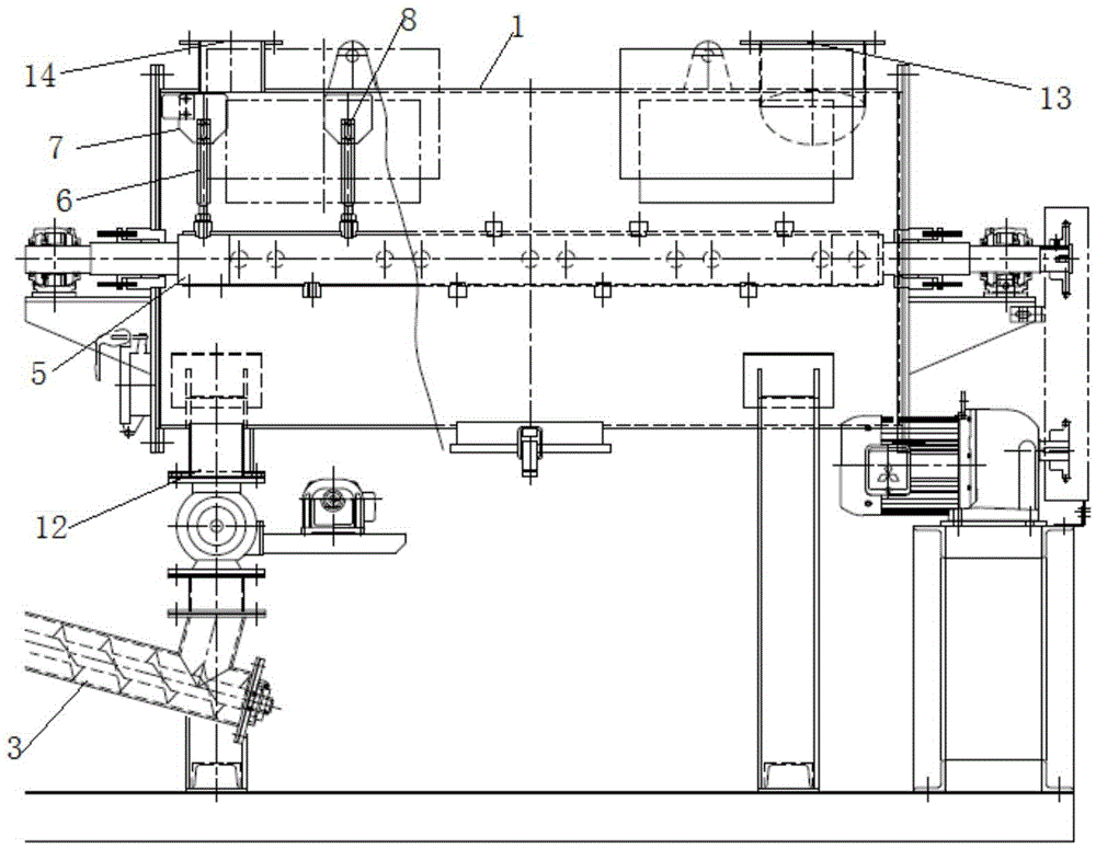
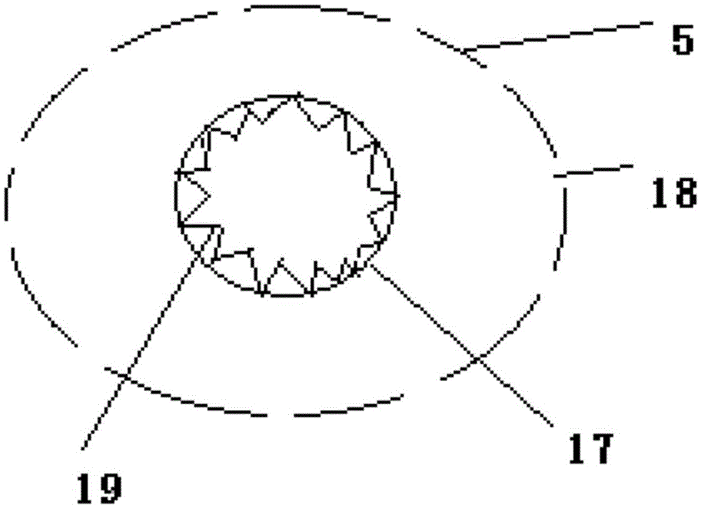
[0040] Such as Figure 1-3 As shown, this embodiment provides a sludge treatment system, including

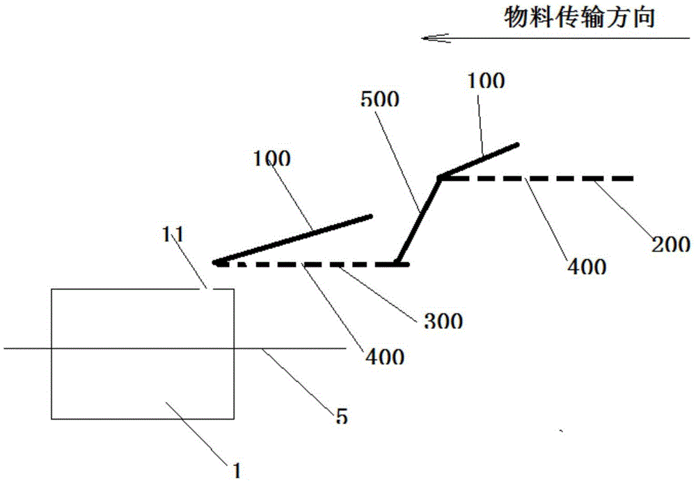
[0041] The transmission device has a three-level transmission surface, the first-level transmission surface is located above the side of the second-level transmission surface, the second-level transmission surface is located above the side of the third-level transmission surface, the first-level transmission surface 200 and the second-level transmission Between the surfaces 300, and between the second-level transmission surface 300 and the third-level transmission surface are respectively connected by a transition device 500, the height between the first-level transmission surface 200 and the second-level transmission surface 300 is smaller than the second-level transmission surface The height between 300 and the third-stage transfer surface, the transfer device can transport the solid-liquid mixed sludge from the first end of the first-stage transfer surface to the end of the fir...


PUM

PropertyMeasurementUnit
angleaaaaaaaaaa

Abstract

The invention relates to a sludge treatment system. The sludge treatment system comprises a transmission device, a water removal structure and a drying device, wherein the drying device comprises a furnace body, a feeding device, a material receiving device, a gas supply device and a stirring device, wherein the feeding device is used for feeding materials into the furnace body, the material receiving device is used for collecting dried materials in the furnace body, the gas supply device is used for introducing external hot gas into the furnace body through a first gas inlet, and the stirring device is used for stirring and grinding the materials. When the materials are dried, hot gas is introduced into a furnace body cavity through the first gas inlet, a second rotating shaft rotates to drive a stirring assembly on the second rotating shaft to continuously stir the materials along the radial and axial directions of the second rotating shaft, and then the materials can roll in the furnace body along the radial and axial directions of the second rotating shaft, so that the stirring time of the materials is prolonged, and the heat convection area between the materials and hot gas is increased; and besides, the materials can be ground into the materials with relatively small particles by the stirring assembly, so that the heat convection area between the materials and hot gas is further increased, and the drying efficiency and drying effect of the materials are improved.

Description

Technical field [0001] The invention relates to the technical field of sludge treatment, in particular to an improved sludge treatment system. Background technique [0002] The sludge is the product of the sewage treatment process, which contains a lot of organic matter, heavy metals and mold, etc. If it is not followed up, it will cause serious pollution to the environment. Therefore, the sludge is often concentrated and dehydrated, but after this treatment The moisture content of the latter sludge is usually above 70%, and the sludge needs to be further dried. [0003] The drying system used in the prior art for sludge drying has a structure like the drying system disclosed in Chinese Patent Document CN201058838Y, including a furnace body, a feeder connected to the inlet of the furnace body, and an air outlet of the furnace body Connected spray tower. The furnace body includes a transmission shaft arranged in the furnace body, and a number of hollow blades arranged on the outer...

Claims


Application Information

Patent Timeline
Patent Type & Authority Applications(China)
IPC IPC(8): C02F11/12
CPCC02F11/12C02F11/121C02F2201/002C02F2303/26
Inventor 王海龙
Owner 中科创新发展(北京)科技有限公司
Why Eureka
Try Eureka