
Novel screw take-up device of belt type conveyor

A belt conveyor and tensioning device technology, applied in the direction of conveyors, transportation and packaging, etc., can solve the problems of reduced service life, inconvenient operation of personnel, bending and deformation of screw rods, etc., and achieve low noise, stable transmission and good use The effect of longevity

Inactive Publication Date: 2016-06-01
JIANGSU HENGYUAN INT ENG CO LTD
View PDF0 Cites 0 Cited by
  • Summary
  • Abstract
  • Description
  • Claims
  • Application Information

AI Technical Summary

Problems solved by technology

This kind of design structure is simple, but there are some disadvantages. Due to the long length of the screw rod, the distance between the force point and the moving point is long, and a large torque is required. In addition, the screw rod will be bent and deformed during actual use, reducing the Its service life! In addition, because the distance between the stress point and the moving point is too long, and the on-site layout of the conveyor is generally relatively compact, it will be very inconvenient for personnel to operate.

Method used


Image

  • Novel screw take-up device of belt type conveyor
  • Novel screw take-up device of belt type conveyor
  • Novel screw take-up device of belt type conveyor

Examples


Embodiment Construction

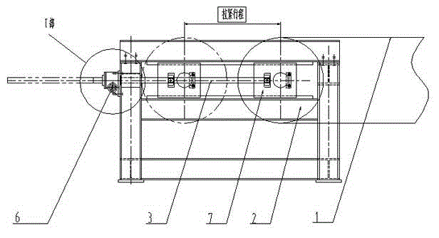
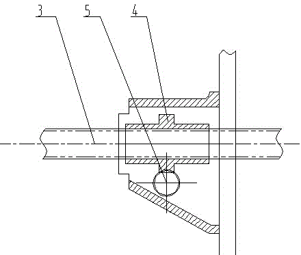
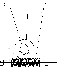
[0015] The present invention includes a drum 2 connected with a belt 1, and the drum 2 is provided with a screw 3 that drives the motion of the drum 2, and the screw 3 is sleeved in a worm wheel 4, and the worm 4 is provided with an internal thread that cooperates with the screw 3; the worm wheel 4 Driven by the worm 5, the worm 5 is externally equipped with a driving mechanism for driving the worm 5 to run.

[0016] The driving mechanism is a rotating nut 6 matched with the worm 5, and the rotating nut 6 is pulled by a wrench.

[0017] The drum 2 is connected with the screw mandrel 3 through a slider 7 .

[0018] The working principle of the tensioning device is as follows:

[0019] The present invention rotates the rotating nut 6 on the screw lifting mechanism with a wrench, thereby driving the worm 5 to rotate, and the worm 5 drives the worm wheel 4 to rotate, and the worm wheel 4 is provided with an internal thread matched with the screw rod 3, and drives the screw rod 3 ...


PUM


Abstract

The invention relates to a novel screw take-up device of a belt type conveyor. The novel screw take-up device comprises rollers (2) connected to a belt (1), wherein a lead screw (3) for driving the rollers (2) to move is arranged on the rollers (2); the lead screw (3) is arranged in a worm wheel (4) in a sleeving mode; inner threads, matched with the lead screw (3), are arranged in the worm wheel (4); the worm wheel (4) is driven by a worm (5); and a drive mechanism for driving the worm (5) to operate is arranged outside the worm (5). The novel screw take-up device has the advantages that firstly, tensioning of the belt can be realized with relatively small moment of force according to the characteristics of worm and gear that transmission ratio is large, transmission is stable and noise is small; secondly, precise tensioning of the belt is realized by being fitted with lead screw transmission and utilizing precise characteristic of the lead screw transmission; and thirdly, by adopting a worm and gear structure, a rotary nut can be arranged on the lower part of a rack, and therefore, operation bystaff is convenient, and layout of the conveyor is not affected.

Description

technical field [0001] The application of the present invention relates to a belt conveyor for minerals, which is a belt conveyor screw tensioning device. Background technique [0002] Belt conveyor is a kind of conveying equipment widely used in modern cement, coal, ports and mines, etc. It has the advantages of simple structure, light weight, large conveying capacity, long conveying distance, low transportation cost, and simple operation and maintenance! [0003] After the belt conveyor is used for a certain period of time, due to the effect of tension, the belt will relax to a certain extent and slip and other phenomena will occur, which will affect the work of the conveyor, so a spiral tensioning device will be designed. By adjusting the screw tensioning device, the belt is kept in a tensioned state, so that the conveyor runs smoothly. [0004] But some screw tensioning devices of present, because the length of screw mandrel is longer, and generally by turning the turni...

Claims


Application Information

Patent Timeline
Patent Type & Authority Applications(China)
IPC IPC(8): B65G23/44
Inventor 刘海明金鹏胡佩曹波
Owner JIANGSU HENGYUAN INT ENG CO LTD
Learn More