Method for automatic switching of emergency power supply of series network

A backup power self-introduction and series network technology, which is applied in the direction of emergency power supply arrangement, power network operating system integration, electrical components, etc., can solve problems such as failure to restore power supply, and achieve the effect of expanding usability and improving reliability

Inactive Publication Date: 2016-05-25
JIANGSU WISCOM TECHNOLOGY CO LTD
View PDF2 Cites 5 Cited by
  • Summary
  • Abstract
  • Description
  • Claims
  • Application Information

AI Technical Summary

Problems solved by technology

However, for multiple substations that are gradually appearing and increasing in the power grid and are supplied in series with a chain structure, the conventional standby automatic switching device in each substation can only realize the backup power automatic switching function of the station as an open-loop point when the main power supply fails. , while other substations at non-open-loop points cannot restore power supply by the conventional standby self-injection device of the station when the power is lost because there is no backup power switch in the station

Method used


Image

  • Method for automatic switching of emergency power supply of series network
  • Method for automatic switching of emergency power supply of series network
  • Method for automatic switching of emergency power supply of series network

Examples


Embodiment Construction

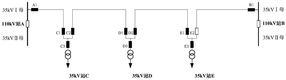
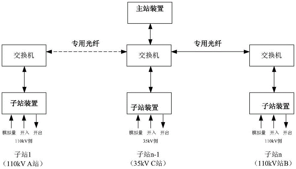
[0016] The general chain structure of the series power supply network such as figure 1 , what is shown here is the series connection of 3 35KV substations of the same voltage level. In actual working conditions, there can be n substations of the same voltage level in series. by figure 1 For example, according to the principle of layered control to configure the network backup and self-switching system, only one control master station is set at the 110kVA station or B station, or any one of the 35kVC, D, and E stations (note that there is only one serial supply circuit). master station), a control sub-station is set in 110kV stations A, B and 35kV stations C, D, E. The control master station mainly completes the function of network backup power supply self-switching, and each control sub-station mainly completes the function of conventional backup and self-switching, as well as the collection, judgment and execution of local data.

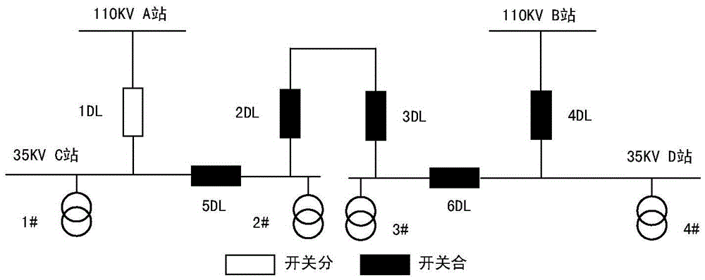
[0017] The framework of the network backup ...


PUM


Abstract

The invention relates to a method for automatic switching of an emergency power supply of a series network. A power grid is formed by n substations which are connected in series and have same voltage grade; when a fault occurs in the power grid, comprehensive logic judgment is carried out to determine a fault position according to panoramic energization information, received in real time, of the substation series network, a fault isolation scheme is executed, and a switch of the emergency power supply is rapidly switched on, so that a power supply network is rapidly and accurately recovered; a series power supply loop is formed by n substations which are connected in series and have same voltage grade, only a master station is arranged, and each of the substations with same or different voltage grades is provided with a control sub-station; the control master station is used for completing the automatic switching function of the emergency power supply of the network, and each control sub-station is mainly used for completing conventional automatic switching and functions of acquiring, judging and executing local data; and when the fault occurs in the power grid, the comprehensive logic judgment is carried out to determine the fault position according to the panoramic energization information, received in real time, of the series network, the fault isolation scheme is executed, the switch of the emergency power supply is rapidly switched on, so that the power supply network is rapidly and accurately recovered.

Description

technical field [0001] The invention relates to a power supply device, in particular to a new method for realizing a self-injection system of a serial network backup power supply. Background technique [0002] In order to ensure the continuous and reliable power supply of the grid, the substation is generally equipped with an equipment self-switching device. When the main power supply fails, the main power supply switch can be tripped and the backup power switch can be put into operation. Undoubtedly, the backup self-switching device plays a key role in the rapid restoration of power supply when the power grid fails. However, for multiple substations gradually appearing and increasing in the power grid, the conventional standby automatic switching device in each substation can only realize the backup power automatic switching function when the main power supply fails when the main power supply is lost. , while other substations at non-open-loop points cannot restore power s...

Claims


Application Information

Patent Timeline
IPC IPC(8): H02J9/06
CPCH02J9/061H02J9/068Y02B70/30Y04S20/20
Inventor 陈晓宇汤一鑫陈冬霞
Owner JIANGSU WISCOM TECHNOLOGY CO LTD
Why Eureka
Try Eureka