Anti-lightning protection components
A protection component and anti-lightning strike technology, which is applied in the direction of electrical components, emergency protection devices, emergency protection circuit devices, etc., can solve the problem that the anti-lightning strike performance cannot be improved, and achieve the effect of improving the anti-lightning strike performance
- Summary
- Abstract
- Description
- Claims
- Application Information
AI Technical Summary
Problems solved by technology
Method used
Image
Examples
Embodiment 1
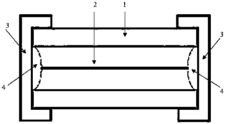
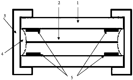
[0018] like figure 2 As shown, it is a miniature anti-lightning protection component, including insulator 1, melt 2, electrode 3, solder 4, and metal lightning protection structure 5. A square metal cap placed on it. Set at both ends of the insulator 1, the two ends of the melt 2 are fixed in the middle of the electrodes 3 at both ends by solder 4 and electrically connected with the electrodes 3 at both ends.
[0019] At least one metal lightning protection structure 5 is provided near the solder 4 in the storage chamber of the insulator 1. In this embodiment, metal lightning protection structures 5 are provided on the four walls of the storage chamber, that is, the entire protection element is provided with 8 metal lightning protection structures were installed 5. The metal lightning protection structure 5 is a thin metal sheet or metal film. In this embodiment, it is a copper foil tape, which is made into a square piece with a size of 2mm*2mm. Copper foil tape, the micro...
Embodiment 2
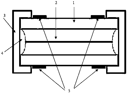
[0024] like image 3 As shown, the difference from Embodiment 1 is that the metal lightning protection structure 5 is a metal film / or a thin metal sheet, which is arranged on the outer wall of the insulating tube 1 close to the electrodes 3 at both ends by printing, electroplating, pasting, etc. , not in contact with the electrodes 3 at both ends. The metal lightning protection structure 5 is preferably made of a copper film by electroplating, or a silver film by printing, or pasted with a copper foil tape.
[0025] In the above two embodiments, the metal lightning protection structure 5 can also be a disc or other shapes, and it can also be a ring shape arranged on the inner wall or outer wall at both ends of the insulating tube 1 and close to the electrode 3, but it must be ensured that they are close to each other. The metal lightning protection structures 5 of the electrodes 3 at both ends are not in contact, otherwise the fusing performance of the protection element may ...
Embodiment 3
[0028] like Figure 4 As shown, a chip type miniature anti-lightning protection component includes an insulating substrate 6, a melt 2 carried on the top surface of the insulating substrate and electrodes 3 located at both ends of the insulating substrate, and the melt 2 is between the electrodes at both ends and connected to the The electrodes 3 at both ends form an electrical connection. The insulating protective layer 7 covers the melt 2 and does not cover the electrodes 3. The metal lightning protection structure 5 is arranged on the side of the substrate in the area where no electrodes are arranged at both ends. The place close to the electrodes is not in contact with the electrodes. Alternatively, the fuse contacts are not covered by the insulating protective layer 7, and the lightning protection structures respectively arranged near the electrodes at both ends are not in contact with each other. The metal lightning protection structure 5 is a metal thin film / or a thin m...
PUM
 Abstract
Description
Claims
Application Information
 - R&D
- Intellectual Property
- Life Sciences
- Materials
- Tech Scout
- Unparalleled Data Quality
- Higher Quality Content
- 60% Fewer Hallucinations
Browse by: Latest US Patents, China's latest patents, Technical Efficacy Thesaurus, Application Domain, Technology Topic, Popular Technical Reports.
© 2025 PatSnap. All rights reserved.Legal|Privacy policy|Modern Slavery Act Transparency Statement|Sitemap|About US| Contact US: help@patsnap.com


