charging clutch
A technology of clutches and conductive parts, which is applied in the direction of circuits, electrical components, coupling devices, etc., can solve problems such as circuit failures and damages of electrical equipment, and achieve the effects of avoiding failures or damages, simplifying structures, and improving work reliability
- Summary
- Abstract
- Description
- Claims
- Application Information
AI Technical Summary
Problems solved by technology
Method used
Image
Examples
Embodiment 1
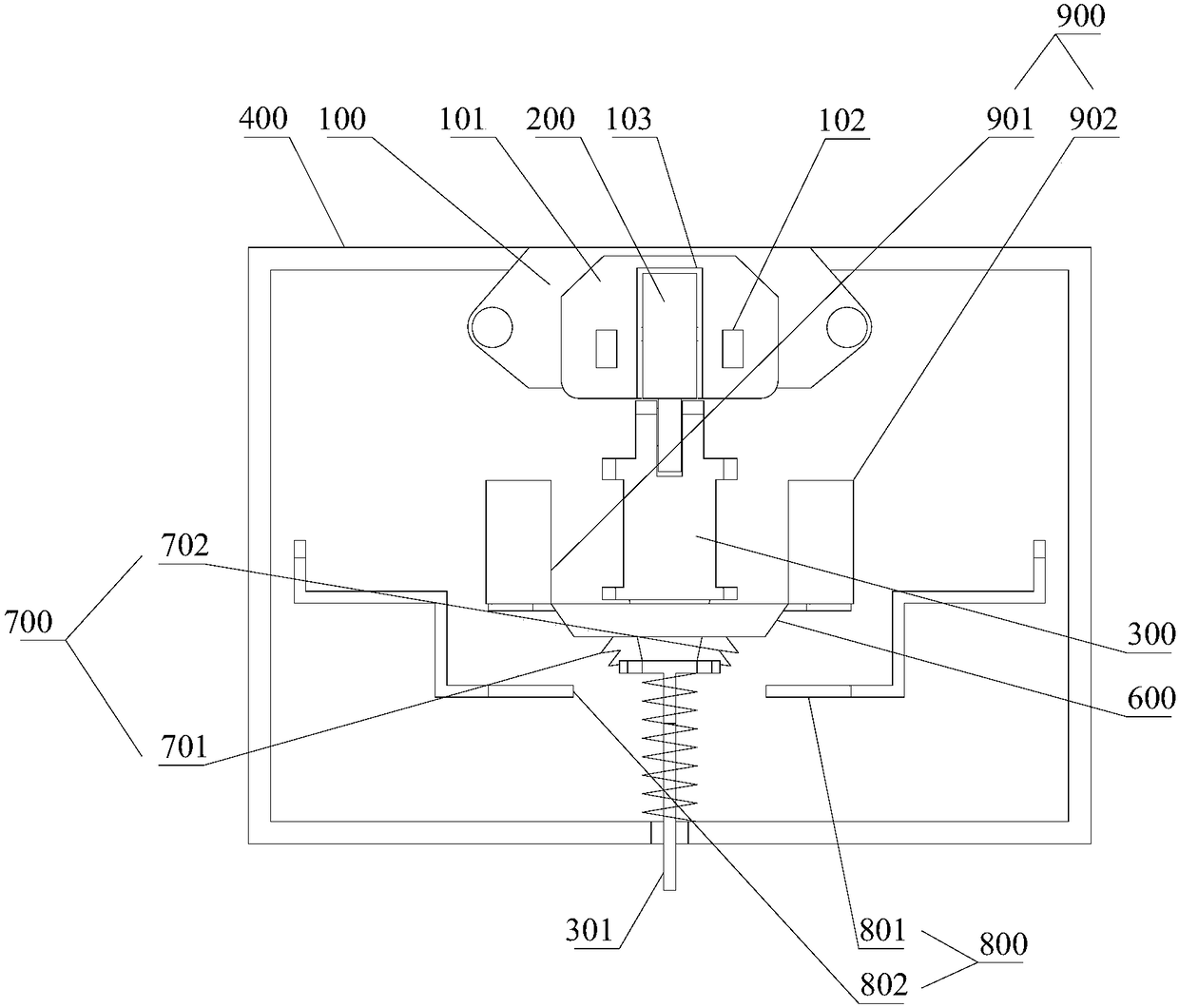
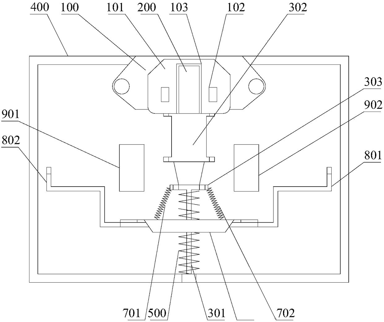
[0061] For the electrical equipment powered by a rechargeable battery, it has an interface for connecting with a power supply plug. However, the existing interface can only be connected with the charging circuit of the electric device, and other circuits of the electric device are in a conducting state during the charging process. During the charging process, the battery heats up, which can easily lead to failure or even damage to other circuits in the conduction state.
[0062] In order to improve the above problems, this embodiment provides a charging clutch. It should be noted that, in order to enable those skilled in the art to understand the charging clutch more clearly, this embodiment uses the charging clutch for electric bicycles for illustration, which does not mean that the charging clutch can only be used for electric bicycles. Charging clutches can be used in various electrical equipment, such as electric motorcycles, electric cars, etc.
[0063] The front descri...
Embodiment 2
[0080] This embodiment is basically the same as Embodiment 1, except that this embodiment uses a different reversing device.
[0081] Such as Figure 7 As shown, the reversing device 700 includes a first electromagnet assembly 703 , a second electromagnet assembly 704 , a first proximity sensor 705 and a second proximity sensor 706 . The first proximity sensor 705 is electrically connected to the first electromagnet assembly 703 , and the second proximity sensor 706 is electrically connected to the second electromagnet assembly 704 .
[0082] The first electromagnet assembly 703 is arranged in front of the connection part 600 , and the second electromagnet assembly 704 is arranged in the rear of the connection part 600 .
[0083] A first protrusion 305 and a second protrusion 306 are disposed on a side of the support block 302 . When the pusher 300 moves backward to the end of the stroke, the first protrusion 305 approaches the first proximity sensor 705, the first proximity...
Embodiment 3
[0085] This embodiment is further described on the basis of Embodiment 1 or 2.
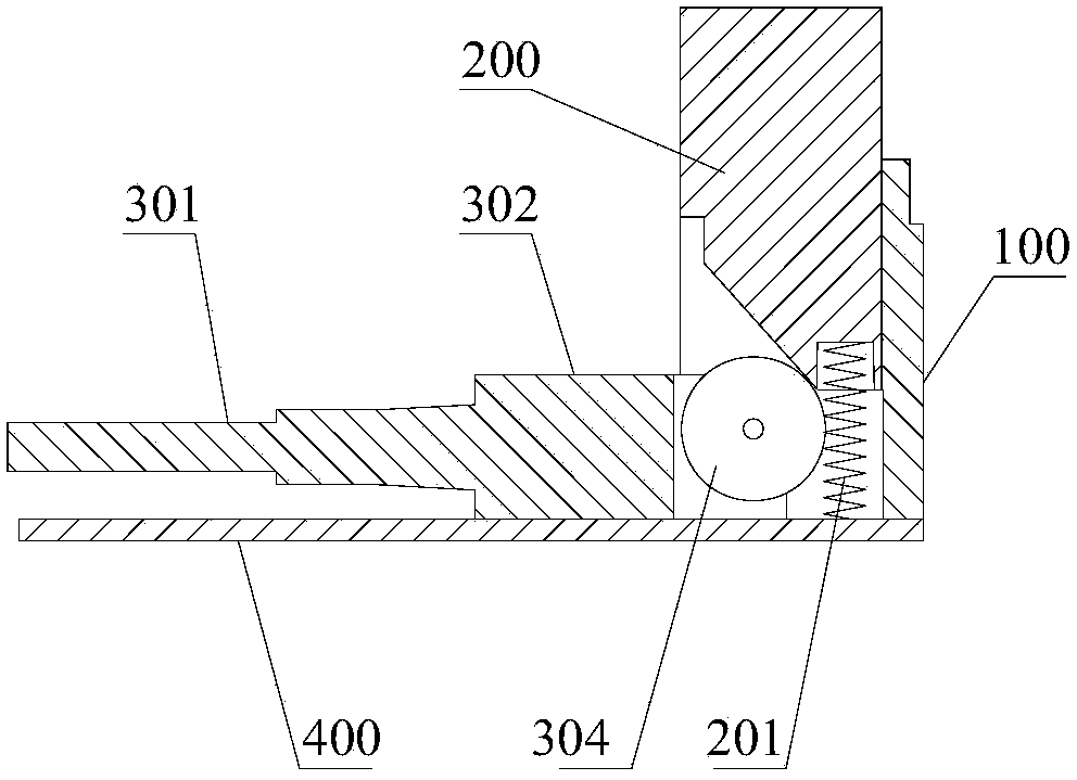
[0086] Such as image 3 with Figure 4 As shown, a roller 304 is provided at the end of the support block 302 , and the roller 304 is in contact with the inclined surface at the bottom of the pressing member 200 . In this way, the friction between the pressing part 200 and the pushing part 300 is reduced, the life of the pressing part 200 and the pushing part 300 is improved, and the movement of the pressing part 200 and the pushing part 300 is smoother, avoiding stagnation.
[0087] Naturally, the rollers can also be arranged at the end of the pressing member 200 and make it contact with the inclined surface at the end of the supporting block 302 .
PUM
 Abstract
Description
Claims
Application Information
 - R&D Engineer
- R&D Manager
- IP Professional
- Industry Leading Data Capabilities
- Powerful AI technology
- Patent DNA Extraction
Browse by: Latest US Patents, China's latest patents, Technical Efficacy Thesaurus, Application Domain, Technology Topic, Popular Technical Reports.
© 2024 PatSnap. All rights reserved.Legal|Privacy policy|Modern Slavery Act Transparency Statement|Sitemap|About US| Contact US: help@patsnap.com


