
Multifunctional Lenz law demonstration apparatus

A technology of Lenz's law and demonstration device, which is applied in the direction of educational appliances, instruments, teaching models, etc., can solve the problems of single demonstration form and difficulty in adapting, and achieve the effect of improving hands-on ability

Active Publication Date: 2016-05-25
HENAN NORMAL UNIV
View PDF4 Cites 3 Cited by
  • Summary
  • Abstract
  • Description
  • Claims
  • Application Information

AI Technical Summary

Problems solved by technology

At present, the demonstration form in the relevant teaching classroom is relatively simple, and the change of the current in the solenoid cannot cause the conductor in the solenoid to generate a magnetic field opposite to the change, so that the conductor moves; nor can the experimental demonstration be used effectively to make the students' image and This experimental phenomenon is intuitively observed, so it is difficult to adapt to the requirements of quality education in the new era

Method used


Image

  • Multifunctional Lenz law demonstration apparatus
  • Multifunctional Lenz law demonstration apparatus
  • Multifunctional Lenz law demonstration apparatus

Examples


Embodiment 1

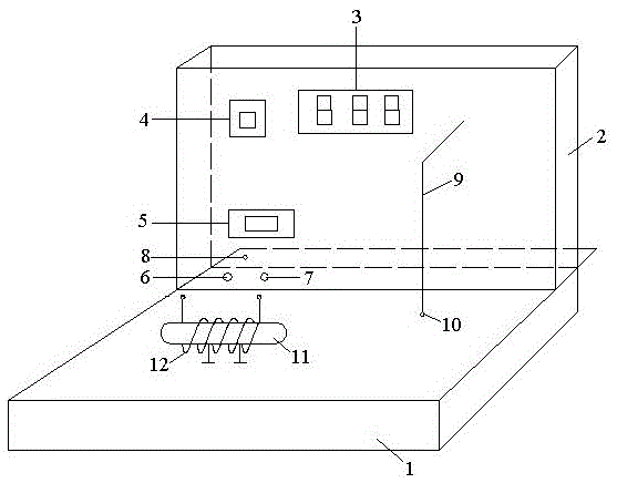
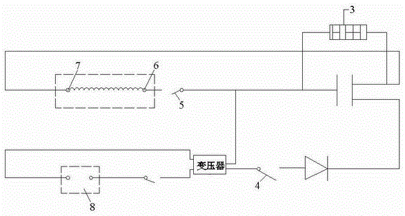
[0014] Connect the output terminal and input terminal of the first coil to the first terminal and the second terminal respectively, and connect the power interface to the mains, close the first switch to charge the capacitor, and observe the display displayed in parallel with the capacitor to No longer change, turn off the first switch, close the second switch, the capacitor discharges, the first coil generates a large current instantaneously, and a magnetic field is generated inside it, and the metal ring suspended on the vertical box through the silk thread will generate a The magnetic field with the opposite direction of the internal magnetic field, these two opposite magnetic fields will generate electromagnetic repulsion, which can eject the metal ring for a certain distance, thus verifying Lenz's law: the magnetic field of the induced current always hinders the change of the magnetic flux that causes the induced current, and at the same time The magnetic field generated b...

Embodiment 2

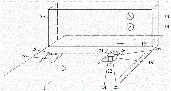
[0016] Connect the output terminal and input terminal of the second coil to the fifth terminal and the sixth terminal respectively, close the third switch, observe the running condition of the mobile trolley to judge the direction of the magnetic field line of the second coil at this time, combine the mobile trolley Pole orientation on the magnetic strip, verifying Ampere's law. In addition, replace the second metal rod with a different material, repeat the above operation, and then explore the influence of different media on the magnitude of the electromagnetic field in combination with the operation of the mobile car.

Embodiment 3

[0018] Connect the output terminal and input terminal of the second coil to the third terminal and the fourth terminal respectively, disconnect the third switch, and observe the red LED light and green LED light during the process of moving the trolley towards or away from the fixed trolley , so that the current direction in the second coil can be known, combined with Ampere's law, Lenz's law can be verified: the magnetic field of the induced current always hinders the change of the magnetic flux that causes the induced current, and at the same time, the magnetic direction is verified by the instantaneous current generated in the second coil conversion of electricity.


PUM


Abstract

The invention discloses a multifunctional Lenz law demonstration apparatus. The multifunctional Lenz law demonstration apparatus comprises a horizontal box and a vertical box, wherein the vertical box is arranged in the middle part of the horizontal box; one side of the vertical box is provided with a display, a first switch, a second switch, a first binding post, a second binding post, a power interface and a metal ring which is suspended through a silk thread; a first metal rod is arranged on the horizontal box at the same side; the first metal rod is arranged on one side of the metal ring; a first coil is twisted around the first metal rod; the other side of the vertical box is provided with a red LED lamp, a green LED lamp, a third binding post and a fourth binding post; a horizontal track, a mobile trolley and a fixed trolley are arranged on the horizontal box at the same side; the mobile trolley is slidingly coordinated with the horizontal track; and the fixed trolley is fixed on the horizontal track. Through simple operation, the multifunctional Lenz law demonstration apparatus can visually verify a plurality of classical electromagnetic theory laws, is suitable for research style experimental teaching, and conforms to a teaching idea, in modern education, for advocating improvement of operational ability, observation ability and problem analyzing ability.

Description

technical field [0001] The invention belongs to the technical field of demonstration devices for physics teaching, and in particular relates to a multifunctional demonstration device for Lenz's law. Background technique [0002] At present, the traditional way of demonstrating Lenz's law is: the rectangular coil passes through the vertical plane where the long straight wire with constant current is located vertically and horizontally, and the change of the induced current in the coil is analyzed; When the energized solenoid is approaching or moving away at a constant speed, the change of the closed loop current; a soft iron rod covered with a light aluminum ring is inserted into the solenoid, and the current is switched on and off for the solenoid, and the operation of the light aluminum ring is observed . The above methods are relatively boring, and cannot allow students to clearly observe the experimental results visually and intuitively. [0003] Lenz's law occupies an ...

Claims


Application Information

Patent Timeline
IPC IPC(8): G09B23/18
CPCG09B23/181
Inventor 张计才张小娟张帅康刘童王俭
Owner HENAN NORMAL UNIV
Learn More