
Optical driving flexible adjustable grating and preparation method thereof

An optical drive and grating technology, applied in the direction of diffraction grating, optics, optical components, etc., can solve the problems of inapplicable flammable and explosive gas spectrum monitoring, high requirements, and difficult to move, etc., to achieve real-time all-optical drive tuning, The effect of a wide range of grating period changes

Inactive Publication Date: 2016-05-25
XI AN JIAOTONG UNIV
View PDF4 Cites 12 Cited by
  • Summary
  • Abstract
  • Description
  • Claims
  • Application Information

AI Technical Summary

Problems solved by technology

Mechanical tuning is to use equipment such as a translation stage to move along the direction of the grating lines to realize the periodic tuning process of the adjustable grating. The requirements for the equipment are very high, and the system is large in size and difficult to move; The grating is electrically driven to change its grating period, so as to achieve the purpose of changing the direction of the diffracted beam. However, if the electrostatic force or piezoelectric type is used to drive the adjustable grating, the sweeping range of the diffraction angle can only be limited to milliradians, and the amount of change in the grating period Only a few nanometers, the required analog voltage is very large, which cannot meet the actual needs
[0004] Temperature tuning mainly changes the temperature of the grating material by means of electric heating. When the power is turned on or off, the temperature of the grating changes and the grating cycle changes. However, there is still a current or voltage input in this method, and there are safety hazards such as circuit short circuit and discharge. , not suitable for spectral monitoring of flammable and explosive gases

Method used


Image

  • Optical driving flexible adjustable grating and preparation method thereof
  • Optical driving flexible adjustable grating and preparation method thereof
  • Optical driving flexible adjustable grating and preparation method thereof

Examples


Embodiment Construction

[0026] The present invention will be further described in detail below in conjunction with specific embodiments, which are explanations of the present invention rather than limitations.

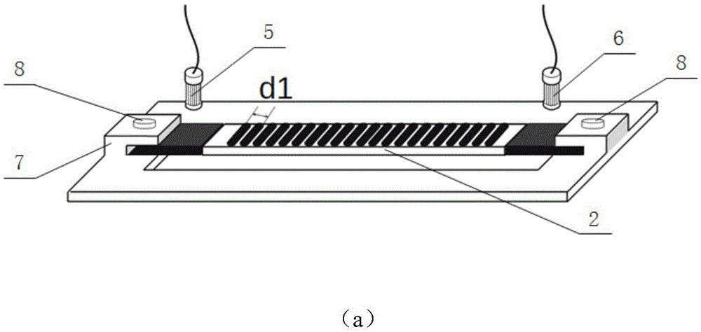
[0027] see figure 2 , a light-driven flexible tunable grating disclosed in the present invention consists of a polydimethylsiloxane film 3 and a graphene-polydimethylsiloxane film 4 arranged at both ends of the polydimethylsiloxane film 3 Composition; under the irradiation of a near-infrared laser, the graphene-polydimethylsiloxane film of the flexible tunable grating 2 can be stretched and deformed to change the grid spacing. The near-infrared laser irradiates the graphene-polydimethylsiloxane film to change the grid pitch of the flexible adjustable grating 2 .

[0028] At the bottom of the flexible adjustable grating 2, there is a grating template 1 for fixing the grid spacing, such as figure 1 shown.

[0029] Such as image 3 As shown in (a) and (b), the flexible tunable grating invol...


PUM


Abstract

The invention relates to an optical driving flexible adjustable grating and a preparation method thereof. The optical driving flexible adjustable grating is characterized in that the middle part is a polydimethylsiloxane film; two ends are graphene / polydimethylsiloxane films; two sides are fixed on a clamp; and the distance between grids can change following changes of light intensity and irradiation time of irradiation of a first 808nm near-infrared laser and a second 808nm near-infrared laser on the graphene / polydimethylsiloxane films. The flexible adjustable grating can continuously adjust expansion and transformation of the graphene / polydimethylsiloxane films under the irradiation of the near-infrared lasers, so that the distance between the grids can be changed; the operating wavelength of the flexible adjustable grating can be changed; and real-time and all-optical type drive tuning can be realized.

Description

technical field [0001] The invention belongs to the technical field of diffractive optical elements, in particular to a light-driven flexible adjustable grating and a preparation method thereof. Background technique [0002] Due to the needs of semiconductor processing technology, ordinary gratings are mostly made of inorganic materials such as silicon, silicon dioxide or other oxides, silicon nitride or other nitrides, and the grating pitch is fixed under normal working conditions. , only work in a specific wavelength range. Since the grating itself cannot change the working wavelength, when different light needs to be selected, a different grating needs to be replaced. Different from ordinary gratings, tunable gratings can select different wavelengths of light or deflect a certain wavelength of light at different angles by changing the period, and are widely used in micro-spectrometers, scanners, optical communications and other fields. [0003] At present, the basic tun...

Claims


Application Information

Patent Timeline
Patent Type & Authority Applications(China)
IPC IPC(8): G02B5/18
CPCG02B5/1828G02B5/1847
Inventor 贾书海王飞唐振华汪永林
Owner XI AN JIAOTONG UNIV
Learn More