Fan combination

Active Publication Date: 2016-05-25
深圳市永诚创科技有限公司
View PDF11 Cites 3 Cited by
  • Summary
  • Abstract
  • Description
  • Claims
  • Application Information

AI Technical Summary

Problems solved by technology

The traditional method of combining two cooling fans in series is generally to fix the two fans in series by adding rivets, but this results in additional costs and increases the assembly time

Method used


Image

  • Fan combination
  • Fan combination
  • Fan combination

Examples


Embodiment Construction

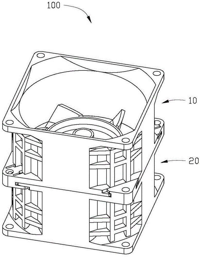
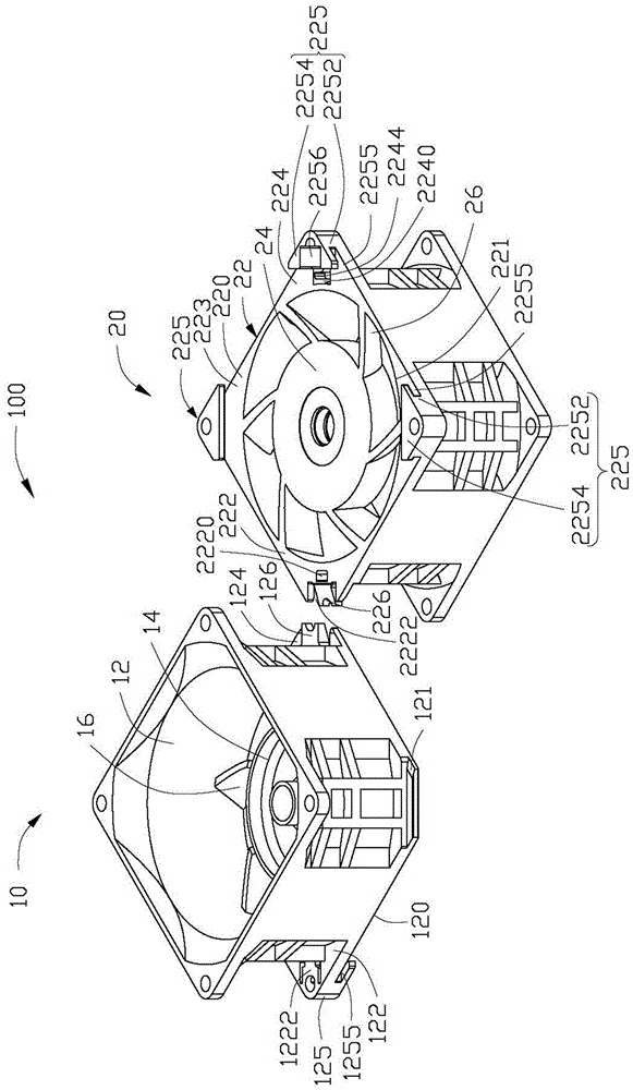
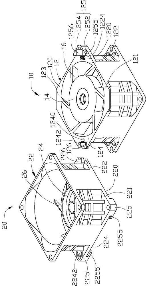
[0013] Figure 1 to Figure 3 A preferred embodiment of a fan assembly 100 of the present invention is shown. The fan assembly 100 includes a first fan 10 and a second fan 20, the first fan 10 and the second fan 20 both include a fan frame 12, 22, and the fan frame 12, 22 of each fan 10, 20 has A fitting surface 120, 220, each fan 10, 20 forms a concave structure (not labeled) and a flange 124, 222 respectively along the two ends of the first direction of the fitting surface 120, 220, the first fan 10 The flange 124 of the second fan 20 relatively moves against the fitting surface 220 of the second fan 20 and is embedded in the concave structure of the second fan 20 , and the flange 222 of the second fan 20 relatively moves against the fitting surface 120 of the first fan 10 and embedded in the concave structure of the first fan 10; an elastic cantilever 1222, 2242 and a button hole 1240, 2220 are formed on the bonding surface 120, 220 of each fan 10, 20, and the elastic canti...


PUM


Abstract

The invention provides a fan combination which comprises a first fan and a second fan, wherein the first fan and the second fan respectively comprise a fan frame; the fan frame of each fan is provided with a binding face; two ends along a first direction of the binding face of each fan are respectively provided with a concave structure and a flange; the flange of the first fan is bound to the binding face of the second fan, can move relative to the second fan and is embedded into the concave structure of the second fan; the flange of the second fan is bound to the binding face of the first fan, can move relative to the first fan and is embedded into the concave structure of the first fan; the binding face of each fan is provided with an elastic cantilever and a buckle hole; the tail end of each elastic cantilever is provided with a clamping block protruded out of the binding face; the clamping block of the elastic cantilever of the first fan is clamped in the buckle hole of the second fan; the clamping block of the elastic cantilever of the second fan is clamped in the buckle hole of the first fan. A combination process of the first fan and the second fan is simple and convenient, and additional rivets are not needed; compared with a fan series-connection combination mode in the prior art, the fan combination provided by the invention has the competitive cost advantage.

Description

technical field [0001] The invention relates to a fan combination, in particular to a serial fan combination. Background technique [0002] With the advancement of science and technology, many electronic components have moved towards miniaturization, high speed and other design features, especially the microprocessor (CPU) in computer products, which attracts consumers to buy with newer and faster features. However, the higher the speed of the CPU, the higher the heat generated. If the heat cannot be taken away from the CPU immediately and quickly, it will often cause the computer to crash, and even the CPU will be damaged due to overheating. In view of this situation, a cooling fan is usually used to dissipate heat from the CPU. [0003] However, the wind pressure generated by a single cooling fan is limited after all, and cannot cope with the heat generated by the CPU. The current practice in the industry is to connect a heat dissipation fan in series with another heat d...

Claims


Application Information

Patent Timeline
Patent Type & Authority Applications(China)
IPC IPC(8): F04D25/16
CPCF04D29/522F04D19/007F04D29/646
Inventor 顾惠莹林显洲胡志锋林永彬
Owner 深圳市永诚创科技有限公司
Why Eureka
Try Eureka