A printing and dyeing water liquid degreasing and filtering device

A technology for oil filtration, printing and dyeing water, which is applied in the direction of grease/oily substance/suspton removal device, liquid separation, separation method, etc. It can solve the problems of unsatisfactory effect and poor automation degree, and achieve good oil removal effect and automation degree high effect

Active Publication Date: 2018-10-30
浙江利明印染有限公司
View PDF5 Cites 0 Cited by
  • Summary
  • Abstract
  • Description
  • Claims
  • Application Information

AI Technical Summary

Problems solved by technology

[0002] The existing printing and dyeing sewage degreasing and filtering method generally adopts the principle that the upper partition and the lower partition are arranged in the box, and the oil floats on the water surface through the flow of water, so that the water at the bottom flows, and the oil at the top The oil is blocked by the upper partition to remove the oil, and then the oil floating on the water is manually removed, the effect is not ideal, and the degree of automation is poor

Method used


Image

  • A printing and dyeing water liquid degreasing and filtering device
  • A printing and dyeing water liquid degreasing and filtering device
  • A printing and dyeing water liquid degreasing and filtering device

Examples


Embodiment Construction

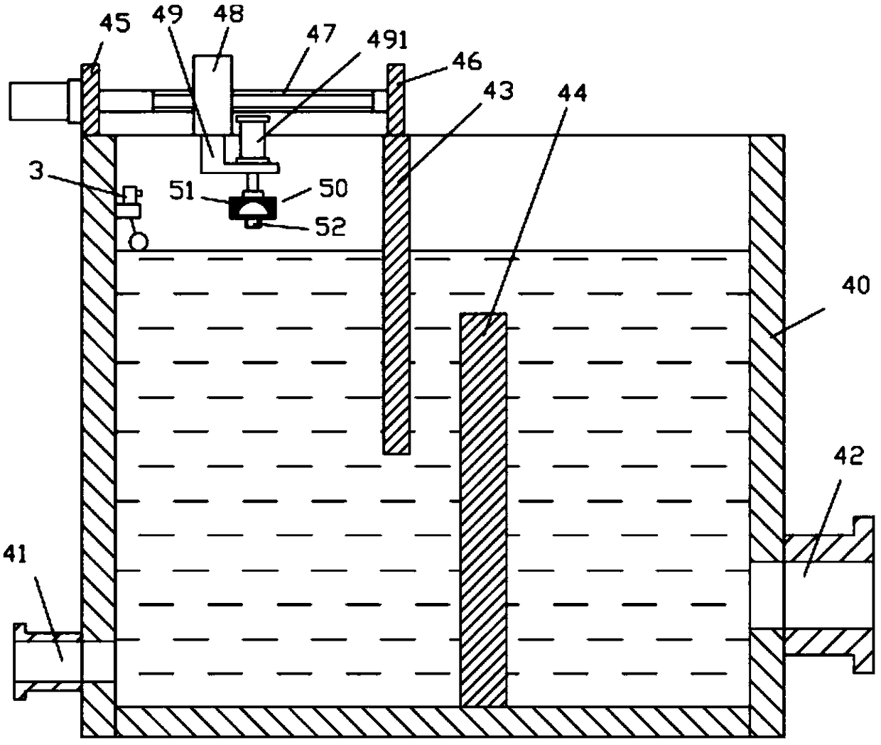
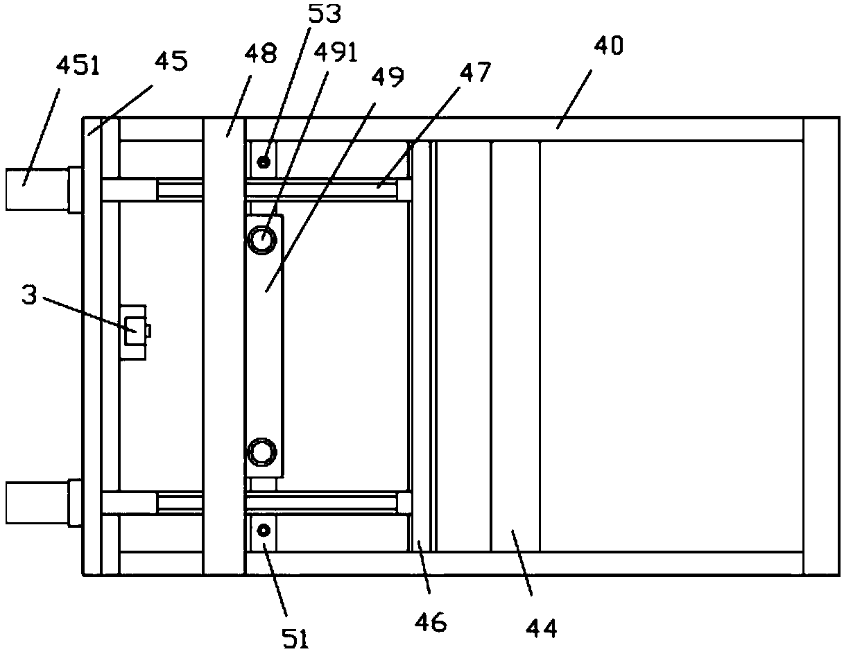
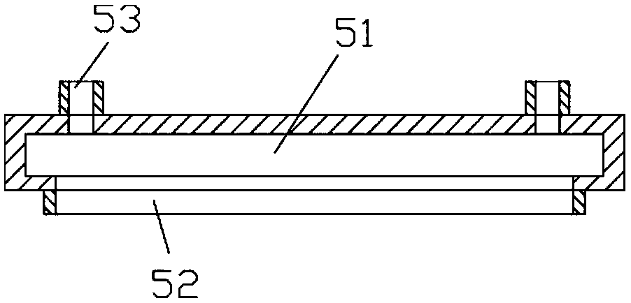
[0016] Examples, see e.g. Figure 1 to Figure 3 As shown, a printing and dyeing water liquid degreasing and filtering device includes a degreasing and filtering box 40, and the lower part of the left side plate of the said degreasing and filtering box 40 is connected with a degreasing liquid inlet pipe 41, and the degreasing and filtering box The bottom of the right side plate of 40 is connected with oil removal liquid outlet pipe 42, and the middle part of oil removal filter casing 40 is fixed with upper dividing plate 43 and lower dividing plate 44, and upper dividing plate 43 is on the left side of lower dividing plate 44, and upper dividing plate 43 The top surface of dividing plate 43 surpasses the upper end surface of degreasing filter casing 40 or is flat with the upper end surface of degreasing filtering casing 40, and the bottom end surface of lower dividing plate 44 is fixed on the bottom plate of filtering casing 40, and upper dividing plate 43 and the two sides of ...


PUM


Abstract

The invention discloses an oil removing and filtering device for printing and dyeing water liquid. The device comprises an oil removing and filtering box body. An oil removing liquid inlet pipe is connected to the lower portion of a left side plate of the oil removing and filtering box body. An oil removing liquid outlet pipe is connected to the lower portion of a right side plate of the oil removing and filtering box body. An upper partition plate and a lower partition plate are fixed to the middle of the oil removing and filtering box body. The upper partition plate is located on the left side of the lower partition plate. The top face of the upper partition plate exceeds the upper end face of the oil removing and filtering box body or is flush with the upper end face of the oil removing and filtering box body. The bottom end face of the lower partition plate is fixed to a bottom plate of the filtering box body. The two side edges of the upper partition plate and the two side edges of the lower partition plate are fixed to the front inner side wall and the rear inner side wall of the oil removing and filtering box body. An oil removing supporting plate is fixed to the top face of the left side plate of the oil removing and filtering box body. An upper oil removing supporting plate is fixed to the top face of the upper partition plate. The two ends of at least two oil removing transmission screws are hinged to the upper oil removing supporting plate and the oil removing supporting plate. Oil on sewage can be automatically accumulated and removed, manual removal is not needed, the oil removing effect is good, and the automation degree is high.

Description

Technical field: [0001] The invention relates to the technical field of printing and dyeing environmental protection equipment, and more specifically relates to a printing and dyeing water liquid degreasing and filtering device. Background technique: [0002] The existing printing and dyeing sewage degreasing and filtering method generally adopts the principle that the upper partition and the lower partition are arranged in the box, and the oil floats on the water surface through the flow of water, so that the water at the bottom flows, and the oil at the top The liquid is blocked by the upper partition to realize degreasing, and then the oil floating on the water is manually fished out, the effect is not ideal, and the degree of automation is poor. Invention content: [0003] The purpose of the present invention is to overcome the deficiencies of the prior art and provide a printing and dyeing water degreasing and filtering device, which can automatically accumulate and r...

Claims


Application Information

Patent Timeline
Patent Type & Authority Patents(China)
IPC IPC(8): C02F1/40
CPCB01D17/0202B01D17/0211B01D17/0214C02F1/40
Inventor 谭儒峰
Owner 浙江利明印染有限公司
Why Eureka
Try Eureka