
Heart rate detecting device

A detection device and technology for heart rate, which are used in telemetry patient monitoring, diagnostic recording/measurement, medical science, etc., can solve the problems of inconvenient physical detection, inability to retain detection data, and unfavorable heart rate evaluation of patients, and achieve low cost and labor saving. Effect

Inactive Publication Date: 2016-05-25
ROMTRONIC INT CO LTD
View PDF0 Cites 4 Cited by
  • Summary
  • Abstract
  • Description
  • Claims
  • Application Information

AI Technical Summary

Problems solved by technology

[0003] However, the existing heart rate detection equipment often requires people to go to the hospital in person to perform the detection. It cannot retain the detection data itself, and cannot monitor for a long time. Inconvenient detection, unable to prevent problems before they happen

Method used


Image

  • Heart rate detecting device
  • Heart rate detecting device

Examples


Embodiment Construction

[0022] In order to express the present invention more clearly, the present invention will be further described below in conjunction with the accompanying drawings.

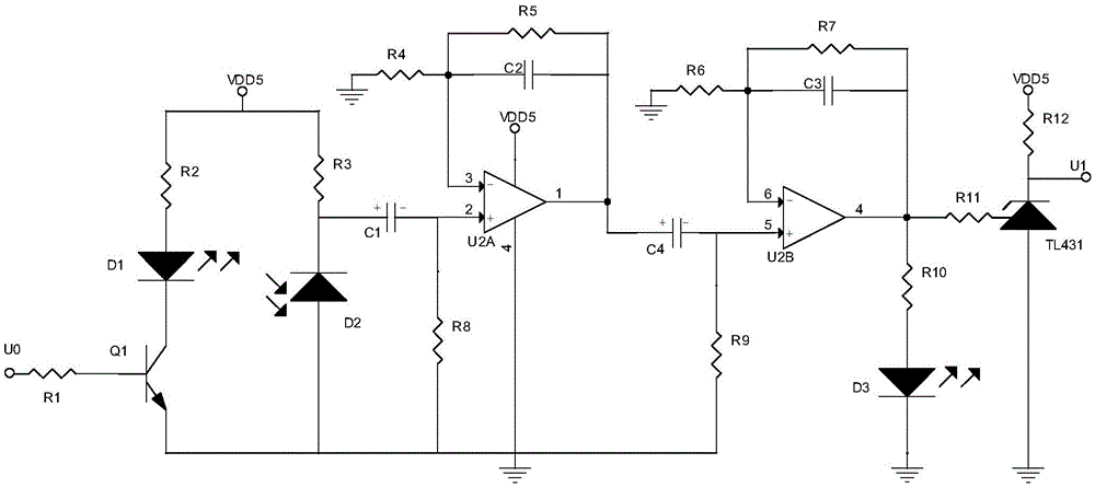
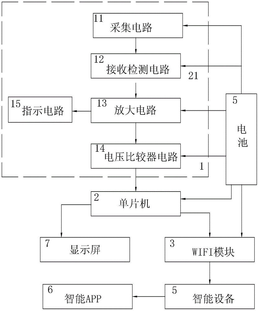
[0023] refer to Figure 1-2 , the heart rate detection device of the present invention includes a finger clip (not shown in the figure), a signal acquisition and amplification circuit 131, a single-chip microcomputer 2, a WIFI module 3 and an intelligent APP6 installed on a smart device 5, the finger clip is connected to a display screen 7, and the finger A battery 4 is installed in the folder; the battery 4 is electrically connected to the signal acquisition and amplification circuit 131, the single-chip microcomputer 2 and the WIFI module 3 respectively;

[0024] The signal acquisition and amplification circuit 131 includes an acquisition circuit 11, a reception detection circuit 12, an amplification circuit 13 and a voltage comparator circuit 14; the acquisition circuit 11 includes a triode Q1, an infrared diod...


PUM


Abstract

The invention discloses a heart rate detecting device which comprises a finger clamp, a signal collecting amplification circuit, a single-chip microcomputer, a WIFI module and APP installed on an intelligent device. The finger clamp is connected with a display screen. A battery is installed in the finger clamp and electrically connected with the signal collecting amplification circuit, the single-chip microcomputer and the WIFI module. The output end of the signal collecting amplification circuit is connected with an external interrupt port of the single-chip microcomputer. The output end of the single-chip microcomputer is electrically connected with the WIFI module and the display screen. The single-chip microcomputer is in wireless communicating connection with the intelligent device through the WIFI module. The intelligent APP obtains heart rate information through the WIFI module. A patient can use the device for detecting the heart rate every day, obtained heart rate data is stored in the intelligent device through the intelligent APP, when it is necessary, the patient directly transmits the heart rate data to a hospital from the intelligent APP, a doctor analyzes the heart rate of the patient within a certain period of time according to the heart rate data, some diseases can be observed easily for a long term, the patient does not need to be hospitalized to be monitored, and labor is saved.

Description

technical field [0001] The invention relates to the technical field of medical devices, in particular to a heart rate detection device capable of long-term detection and extraction of heart rate data. Background technique [0002] With the beating of the heart, the weak fluctuations of the arteries in the fingers of the human body also change accordingly. The weak fluctuation signals in the fingers can be detected by the infrared photoelectric sensor. The infrared photoelectric receiving tube on the other side detects the heart rate fluctuation of the human body and converts it into an electrical signal. Since the frequency of this signal is proportional to the pulse rate of the human body per minute, it can be realized by shaping, counting and displaying the pulse signal. The purpose of real-time monitoring of pulse rate. [0003] However, the existing heart rate detection equipment often requires people to go to the hospital in person to perform the detection. It cannot r...

Claims


Application Information

Patent Timeline
Patent Type & Authority Applications(China)
IPC IPC(8): A61B5/0245
CPCA61B5/0004A61B5/0059A61B5/02433A61B5/02438A61B5/0245A61B5/6826
Inventor 高杰
Owner ROMTRONIC INT CO LTD
Learn More