A Structural Improvement of Pneumatic Ram Door

A technology of structural improvement and pneumatic gate, which is applied in exhaust gas device, combustion product treatment, combustion method, etc., can solve the problems of weak structure, inconvenient maintenance, difficult assembly, etc. Few, easy to assemble effect

Active Publication Date: 2018-04-06
FOSHAN SAINDI ENVIRONMENTAL PROTECTION TECH CO LTD
View PDF6 Cites 0 Cited by
  • Summary
  • Abstract
  • Description
  • Claims
  • Application Information

AI Technical Summary

Problems solved by technology

[0005] This device adopts the method of fixing the cylinder with two seats on the side, which solves the safety hazards caused by the cylinder being too high above the main frame, difficult to assemble, inconvenient to maintain, and weak in structure.

Method used


Image

  • A Structural Improvement of Pneumatic Ram Door
  • A Structural Improvement of Pneumatic Ram Door
  • A Structural Improvement of Pneumatic Ram Door

Examples


Embodiment Construction

[0014] Now in conjunction with accompanying drawing and embodiment the present invention is described in further detail:

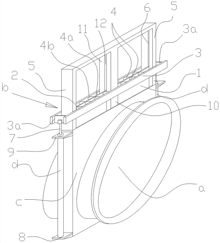
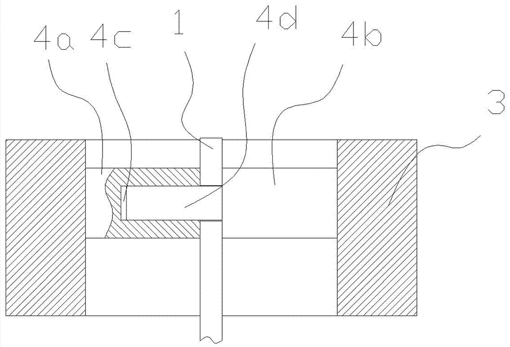
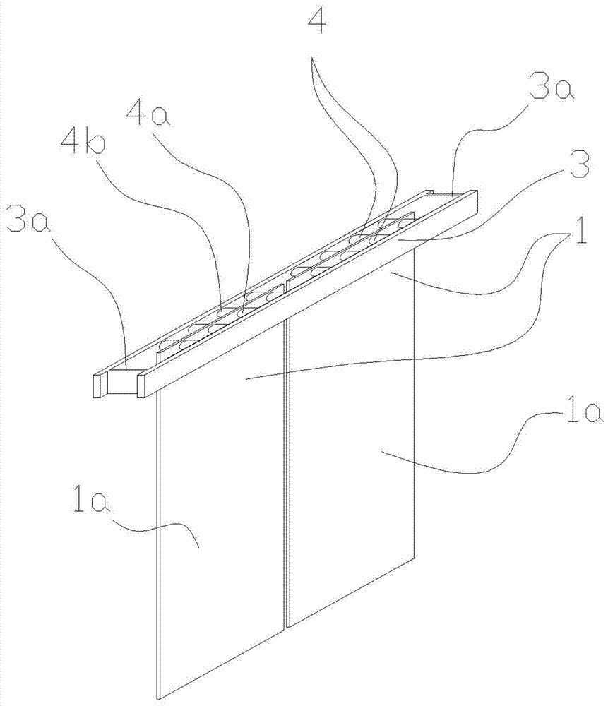
[0015] Such as figure 1 As shown, the present invention includes a ram door b arranged on the flue a, a cylinder d arranged on the main frame c to drive the ram door b to move, and the feature is that the ram door b includes a plate-shaped ram body 1, The splint clamp 2, the splint clamp 2 includes a rectangular frame 3, several pairs of pillars 4 arranged on the inside of the frame 3, each pair of pillars 4 includes a female pillar 4a, a male pillar 4b, and a plate gate body. The upper end of 1 is arranged between the female column 4a and the male column 4b of each pair of columns 4 and is clamped and fixed by the female column 4a and the male column 4b, and the two ends of the frame-like frame 3 float out of the flue a, The columnar racks 5 on both sides of the main frame c on the flue a are respectively guided through the two ends 3a of the frame-like...


PUM


Abstract

An improved structure of a pneumatic gate valve comprises the gate valve arranged on a flue, and an air cylinder arranged on a main frame to drive the gate valve to move. The improved structure of the pneumatic gate valve is characterized by comprising a plate-shaped gate valve body and a gate clamp. The gate clamp comprises a framework and a plurality of pairs of columnar bodies arranged on the inner side of the framework. Each pair of columnar bodies comprise the female columnar body and the male columnar body. The upper end of the plate-shaped gate valve body is arranged between the female columnar body and the male columnar body of each pair of columnar bodies and clamped and fixed by the female columnar bodies and the male columnar bodies. Compared with the prior art, the improved structure of the pneumatic gate valve has the advantages that through grooves do not need to be formed in machine frames on two sides, the strength and rigidity of the whole main frame structure are guaranteed, deformation of the main frame is prevented, the strength of the gate valve is not affected, the occupied space is small, assembly is easy, maintenance is convenience, and safety is good.

Description

Technical field: [0001] The present invention relates to a valve. Background technique: [0002] Such as Figure 4 As shown, at present, the wet desulfurization flue pneumatic ram door is determined by the ram structure, and it is necessary to open slots on both sides of the frame, so that the cylinder can drive the ram to move up and down from the outside, and the two frames are opened from the side. The guide groove will cause deformation of the main frame of the entire gate, affect the strength of the gate, and even affect the opening and closing of the gate and cause the equipment to stop running. Additionally, if Figure 5 As shown, the existing wet desulfurization flue pneumatic ram door, because the cylinder is above the ram door, the cylinder is too high from the ground, which makes installation and maintenance difficult for installers. The biggest hidden danger exists when the structural strength of the cylinder is not strong. There are potential safety hazards, a...

Claims


Application Information

Patent Timeline
Patent Type & Authority Patents(China)
IPC IPC(8): F23J13/08
CPCF23J13/08
Inventor 黄建起
Owner FOSHAN SAINDI ENVIRONMENTAL PROTECTION TECH CO LTD
Why Eureka
Try Eureka