
Construction method of long-span ultra-thick cast-in-place post-tensioning prestressed hollow slab with slow bond

A technology for bonding prestressed and hollow floor slabs, which is applied in floors, buildings, building components, etc., can solve the problems of insufficient structural performance of unbonded prestressed tendons, instability and collapse of formwork supports, steel bars and bottom forms floating up, etc. Good anti-floating effect, reduced concrete consumption and accurate positioning

Active Publication Date: 2018-09-14
JIANGSU HUAJIANG CONSTR GROUP
View PDF3 Cites 0 Cited by
  • Summary
  • Abstract
  • Description
  • Claims
  • Application Information

AI Technical Summary

Problems solved by technology

[0003] In the traditional hollow slab construction technology, most of the anti-floating prefabricated hollow blocks are connected and fixed with the main steel bars, and the buoyancy generated by the prefabricated hollow blocks is transmitted to the steel skeleton. There will be huge buoyancy in the poured concrete. If it is not handled properly, it may cause the steel bars and the bottom form to float up as a whole, and the formwork support will lose stability and collapse; traditional prestressed hollow-core slabs use unbonded prestressed tendons or bonded prestressed reinforcement. Stressed tendons and unbonded prestressed tendons have the disadvantage of insufficient structural performance, while the construction of bonded prestressed tendons needs to arrange tunnels and pressure drop, the process is complex and produces a lot of pollutants

Method used


Image

  • Construction method of long-span ultra-thick cast-in-place post-tensioning prestressed hollow slab with slow bond
  • Construction method of long-span ultra-thick cast-in-place post-tensioning prestressed hollow slab with slow bond
  • Construction method of long-span ultra-thick cast-in-place post-tensioning prestressed hollow slab with slow bond

Examples


Embodiment 1

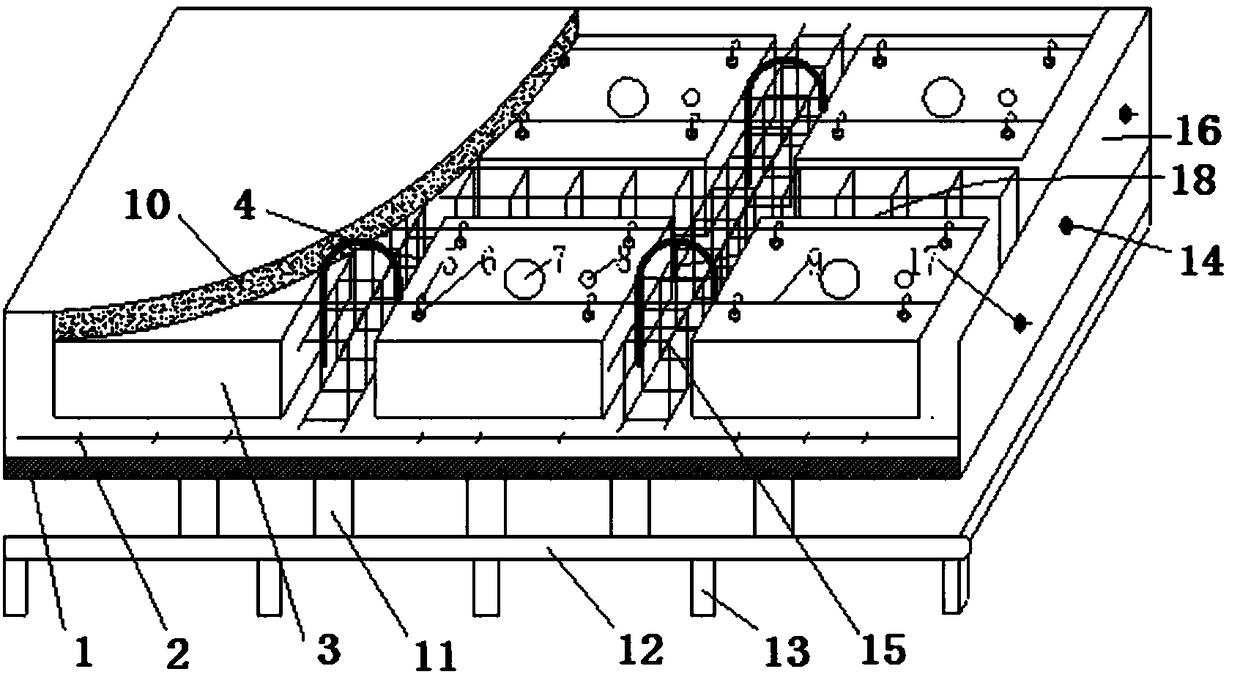
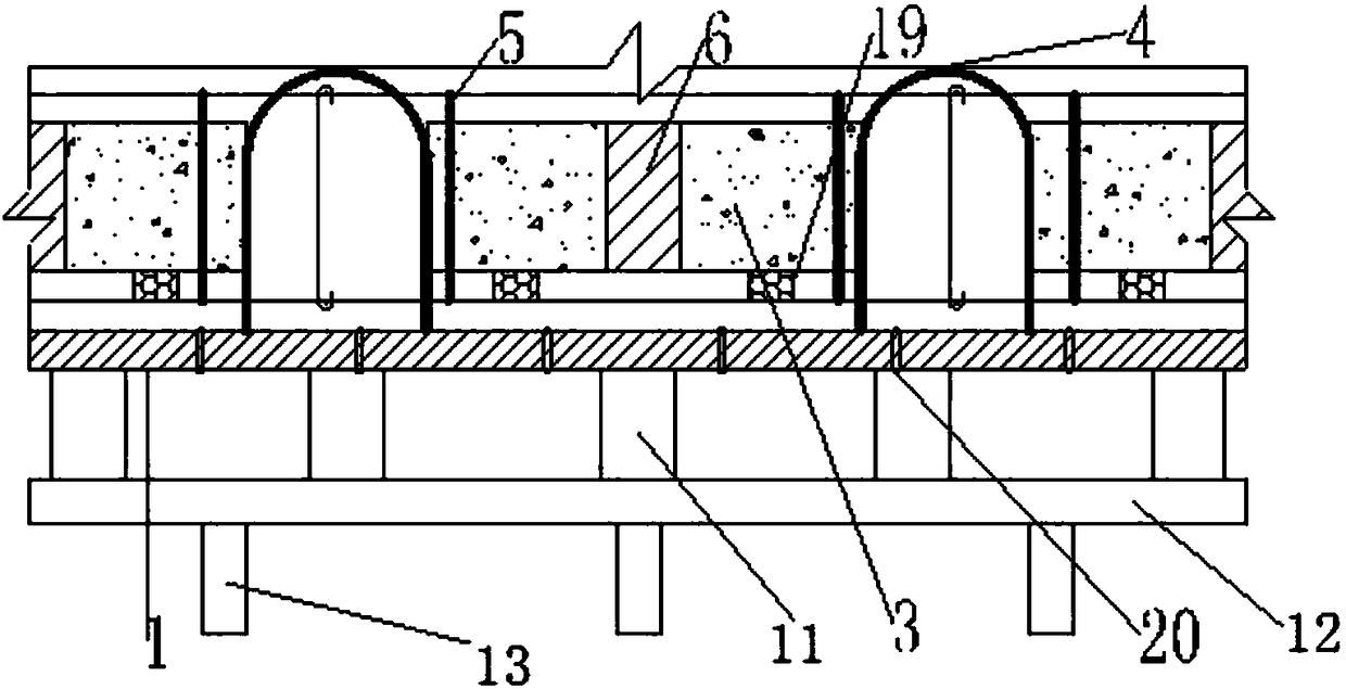
[0032] figure 1 It is a schematic diagram of the super-thick cast-in-situ post-tensioning slowly bonded prestressed hollow floor slab of the present invention; figure 2 It is a cross-sectional view of the invented super-thick cast-in-place post-tensioning slow-bonding prestressed hollow floor. Reference figure 1 , 2 As shown, at the bottom of the ultra-thick cast-in-situ post-tensioning slowly bonded pre-stressed hollow floor slab, a support member is arranged, the support member includes a horizontally arranged steel pipe 12 and a vertical bracket 13, and a bottom mold 1 is set above the support member And the floor reinforcement 2, there are multiple rows and rows of prefabricated hollow blocks 3 arranged above the floor reinforcement 2, and the floor reinforcement is arranged between the prefabricated hollow blocks. The floor reinforcement includes the horizontally arranged floor main reinforcement 14 and the slab rib reinforcement 15, and the bottom mold 1 The side form 16 ...


PUM


Abstract

The invention discloses a construction method for a slowly-bonded hollow prestressing floor slab through a large-span ultra-thick cast-in-place post-tensioning method. The method includes the main construction steps of (1) bottom formwork laying, (2) reinforcing steel bar construction, (3) side formwork installation, (4) prefabricated hollow block installation and reinforcement, (5) concrete pouring, and (6) prestressing tension. Main floor slab reinforcing steel bars are connected with a side formwork, so that the position of a main reinforcing steel bar framework is fixed. Prefabricated hollow blocks are connected with the main floor slab reinforcing steel bars through anti-floating reinforcing steel bars. The good effect is achieved in dealing with floating of the hollow blocks. U-shaped clips are used for locating the hollow blocks in the horizontal direction. Slowly-bonded prestressing reinforcing steel bars are located through locating supports accurately. By the adoption of the construction method, the use amount of concrete is reduced, the construction efficiency is improved, the manufacturing cost is reduced, damage to the environment is reduced, and the economic and social benefits are good.

Description

Technical field [0001] The invention relates to a construction method for a prestressed hollow floor slab, in particular to a construction method for a large-span ultra-thick cast-in-place post-tensioning method to slowly bond the prestressed hollow floor slab. technical background [0002] In recent years, with the substantial improvement of engineering technology and the increasing demand for individualization, the domestic construction market has an increasing demand for open space; the prestressed hollow floor technology has low weight, high rigidity, crack resistance, and strong resistance to deformation. Features, has good adaptability to large-span, large-load structures. [0003] In the traditional hollow floor construction process, the anti-floatation of prefabricated hollow blocks is mostly used to connect and fix the prefabricated blocks with the main steel bars, and the buoyancy generated by the prefabricated hollow blocks is transmitted to the steel frame. However, for...

Claims


Application Information

Patent Timeline
Patent Type & Authority Patents(China)
IPC IPC(8): E04B5/36E04B5/21
CPCE04B5/21E04B5/36
Inventor 王新泉
Owner JIANGSU HUAJIANG CONSTR GROUP
Learn More