
Guard plate and landing gear linkage retracting device

A retractable device and landing gear technology, which is applied in the field of guard plate and landing gear linkage retractable devices, can solve the problems of relatively high requirements for coordinated design of moving parts and installation space, complex implementation of coordinated valve lowering mechanism, etc., to achieve convenient installation And the effect of replacing the support arm, compact structure, and reducing wear

Active Publication Date: 2016-05-18
CHENGDU AIRCRAFT INDUSTRY GROUP
View PDF10 Cites 8 Cited by
  • Summary
  • Abstract
  • Description
  • Claims
  • Application Information

AI Technical Summary

Problems solved by technology

In the design of the aircraft hydraulic system, compared with the design method of using hydraulic solenoid valves for sequential control, the design of the coordinated valve retraction / lowering mechanism has more advantages, which can greatly improve the reliability of retracting and retracting the landing gear, and at the same time effectively reduce the weight and weight of the system. cost, and there is no need for research and implementation of flight control strategies, the system design is more simplified, so the application of the coordinated valve retracting mechanism in the aircraft hydraulic system is very extensive and mature. Compared with the coordinated valve retracting mechanism, the implementation of the coordinated valve lowering mechanism is relatively complicated. Coordinated design of moving parts and relatively high requirements for installation space, so it is still a difficult point in the design of aircraft hydraulic systems, and it is the first time in the design of a certain type of UAV

Method used


Image

  • Guard plate and landing gear linkage retracting device
  • Guard plate and landing gear linkage retracting device
  • Guard plate and landing gear linkage retracting device

Examples


Embodiment 1

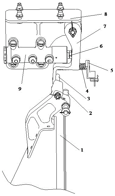
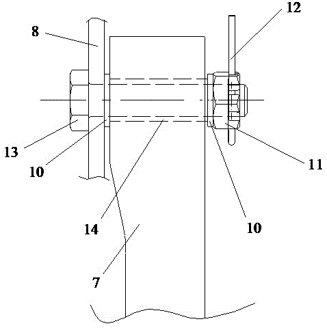
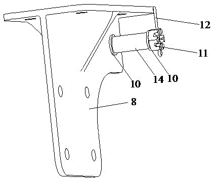
[0034] As a preferred embodiment of the present invention, with reference to the attached figure 1 , figure 2 , image 3 , Figure 4 and Figure 5 As shown, this embodiment discloses a guard plate landing gear linkage retractable device, this embodiment includes:

[0035] A guard plate landing gear linkage retractable device, including a guard plate 1 and a mounting base 8, and also includes a coordination valve 9, an arm 7 and a pressure rod 3, the coordination valve 9 is fixed on the mounting base 8, and the pressure rod 3 is set on the guard plate 1 and fixedly connected with the guard plate 1, one end of the support arm 7 is in contact with the pressure rod 3, and the other end is movably connected with the mounting seat 8, and the support arm 7 and the coordination valve 9 are located in the same installation plane . Also comprise bolt 13, grooved nut 11 and cotter pin 12, all punch through hole on described mount 8 and support arm 7, described bolt 13 passes throug...

Embodiment 2

[0047] As another preferred embodiment of the present invention, refer to the attached figure 1 , figure 2 , image 3 , Figure 4 and Figure 5 , this embodiment discloses a guard plate landing gear linkage retractable device, this embodiment includes:

[0048] A guard plate landing gear linkage retractable device, including a guard plate 1 and a mounting base 8, and also includes a coordination valve 9, an arm 7 and a pressure rod 3, the coordination valve 9 is fixed on the mounting base 8, and the pressure rod 3 is set on the guard plate 1 and fixedly connected with the guard plate 1, one end of the support arm 7 is in contact with the pressure rod 3, and the other end is movably connected with the mounting seat 8, and the support arm 7 and the coordination valve 9 are located in the same installation plane . Also comprise bolt 13, grooved nut 11 and cotter pin 12, all punch through hole on described mount 8 and support arm 7, described bolt 13 passes through the throu...

Embodiment 3

[0051] As another preferred embodiment of the present invention, refer to the attached figure 1 , figure 2 , image 3 , Figure 4 and Figure 5 , this embodiment discloses a guard plate landing gear linkage retractable device, this embodiment includes:

[0052] A guard plate landing gear linkage retractable device, including a guard plate 1 and a mounting base 8, and also includes a coordination valve 9, an arm 7 and a pressure rod 3, the coordination valve 9 is fixed on the mounting base 8, and the pressure rod 3 is set on the guard plate 1 and fixedly connected with the guard plate 1, one end of the support arm 7 is in contact with the pressure rod 3, and the other end is movably connected with the mounting seat 8, and the support arm 7 and the coordination valve 9 are located in the same installation plane .


PUM

PropertyMeasurementUnit
Thicknessaaaaaaaaaa

Abstract

The invention relates to the technical field of aircraft manufacturing, in particular to a guard plate and landing gear linkage retracting device. The guard plate and landing gear linkage retracting device comprises a guard plate, a mounting seat, a coordination valve, a support arm and a pressure rod, wherein the coordination valve is fixed to the mounting seat; the pressure rod is arranged on the guard plate and is fixedly connected with the guard plate; one end of the support arm is in contact with the pressure rod, and the other end is movably connected with the mounting seat; the support arm and the coordination valve are positioned in the same mounting plane. The linkage retracting device disclosed by the invention is compact in structure, low in cost, and simple to use and maintain, the retracting reliability for the landing gear can be greatly improved, besides, the requirement for the mounting space of an aircraft is also low, and the retracting device is easy to popularize and use in a hydraulic system of the aircraft.

Description

technical field [0001] The invention relates to the technical field of aircraft manufacturing, in particular to a guard plate landing gear linkage retractable device. Background technique [0002] Improving the reliability of retracting and retracting the landing gear as much as possible is crucial to ensure the safety of the aircraft and the completion of the mission. Therefore, the guarantee of the retraction sequence of the landing gear struts and guard plates is very critical: that is, when retracting the landing gear, retract the landing gear struts first. Then put up the wheel guard; and when putting down the landing gear, put down the wheel guard first and then put down the landing gear strut. In the design of the aircraft hydraulic system, compared with the design method of sequential control using hydraulic solenoid valves, the design of the coordinated valve retraction / lowering mechanism has more advantages, which can greatly improve the reliability of retracting a...

Claims


Application Information

Patent Timeline
IPC IPC(8): B64C25/20
Inventor 曹宁孙炜王山
Owner CHENGDU AIRCRAFT INDUSTRY GROUP
Learn More