flow switching valve

A flow path switching and valve seat technology, applied in multi-port valves, valve devices, valve details, etc., can solve the problems of easy wear of sliding parts, increased pressure loss, deterioration of sealing performance, etc. Pressure, the effect of reducing pressure loss

Active Publication Date: 2020-06-30
FUJIKOKI MFG CO LTD
View PDF10 Cites 0 Cited by
  • Summary
  • Abstract
  • Description
  • Claims
  • Application Information

AI Technical Summary

Problems solved by technology

[0011] That is, in the sliding flow path switching valve described in Patent Document 1, there is a problem that the high-pressure fluid (refrigerant) collides with the inner wall surface and the like in the valve casing with a small internal volume, and since the flow direction thereof changes greatly, The pressure loss increases, and the flow path is switched due to the sliding of the sliding main spool with a pair of left and right piston seals. The sliding part is easy to wear due to stick-slip, etc. The sealing performance deteriorates, and the valve is prone to leakage

Method used


Image

  • flow switching valve
  • flow switching valve
  • flow switching valve

Examples


Embodiment Construction

[0062] Hereinafter, specific embodiments of the present invention will be described with reference to the drawings.

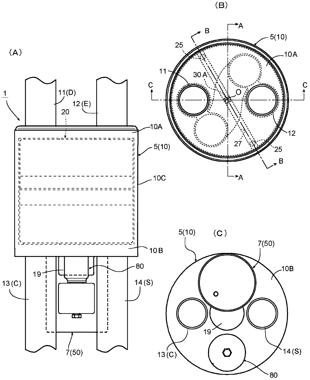
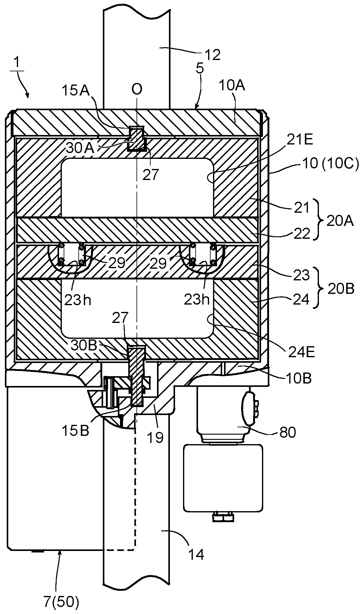
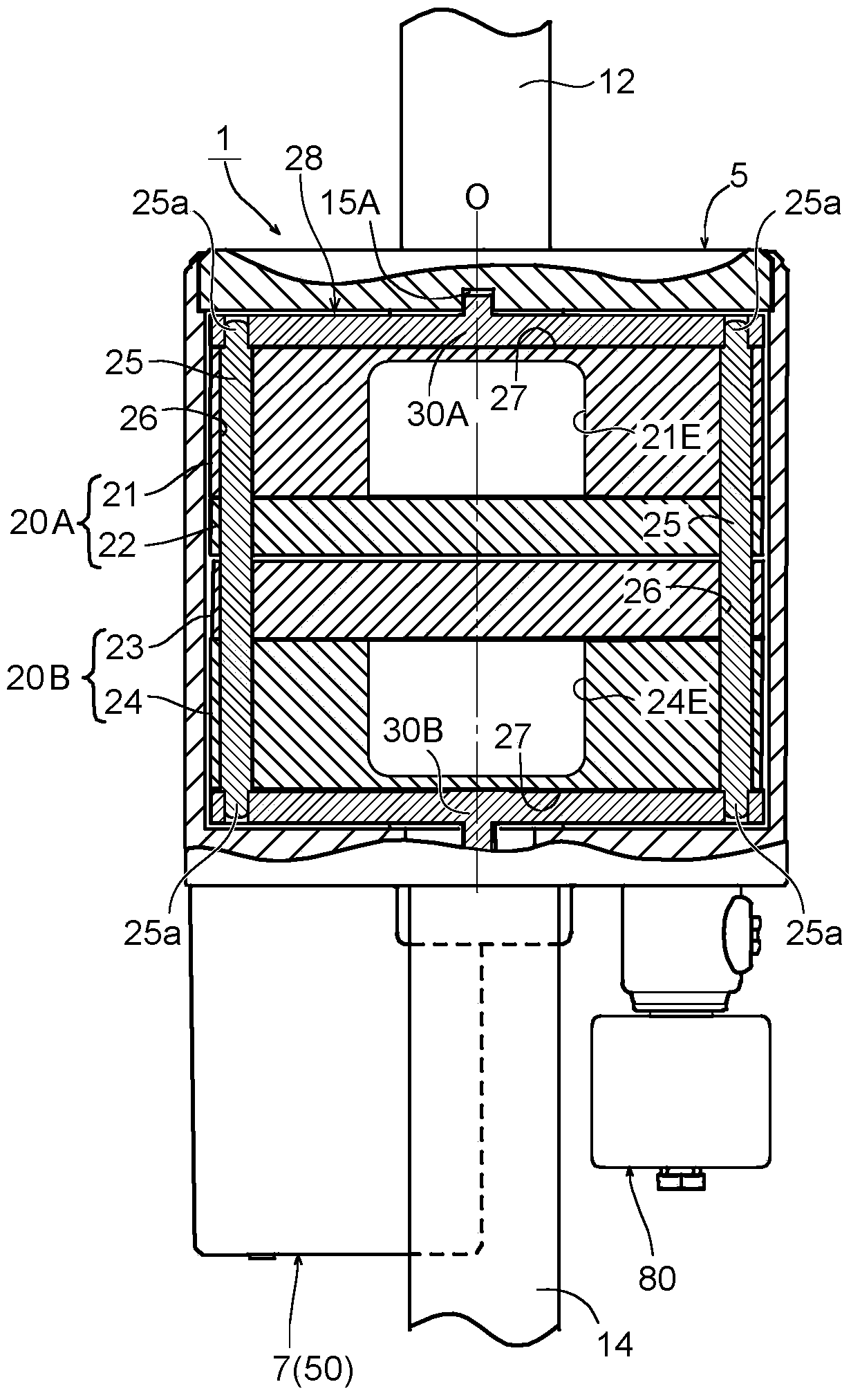
[0063] figure 1 The first embodiment of the channel switching valve according to the present invention is shown, (A) is a side view, (B) is an upper surface side configuration diagram, and (C) is a lower surface side configuration diagram. in addition, figure 2 , image 3 , Figure 4 respectively figure 1 In (B), another side view of the partial fracture along the line A-A, another side view of the partial fracture along the line B-B, and an enlarged cross-sectional view of the main valve part along the line C-C.

[0064] In addition, in this specification, the expression of positions and directions such as up and down, left and right, front and rear are added for the convenience of the drawings in order to avoid cumbersome description, and do not limit the positions and directions in the state of actual assembly in the heat pump cooling and heating syst...


PUM


Abstract

PROBLEM TO BE SOLVED: To provide a flow channel switch valve capable of minimizing pressure loss and abrasion of a sliding part, improving sealability, preventing valve leakage, improving durability by securing sufficient strength to endure high pressure, further improving pipe arrangement, and reducing an occupation space.SOLUTION: A flow channel switch valve includes a main valve having a cylindrical main valve housing of which upper and lower openings are air-tightly sealed by a plate-shaped upper valve seat 10A and a lower valve seat, at least three in total of ports 11, 12, 13, 14 formed on the upper valve seat 10A and / or the lower valve seat, a columnar main valve element rotatably disposed in the main valve housing, and an actuator for rotating the main valve element. A plurality of communication passages 31-34 to selectively communicate the ports, are disposed in the main valve element, and the communicated ports are switched by rotating the main valve element.SELECTED DRAWING: Figure 6

Description

technical field [0001] The present invention relates to a rotary flow path switching valve for switching the flow path by rotating a valve core, in particular to a flow path switching valve suitable for flow path switching in heat pump cooling and heating room systems and the like. Background technique [0002] In general, heat pump cooling and heating systems such as room air conditioners and car air conditioners include not only compressors, outdoor heat exchangers, indoor heat exchangers, expansion valves, etc., but also flow paths as flow path (flow direction) switching components. switch valve. [0003] refer to Figure 24 , an example of a heat pump type cooling and heating room system equipped with such a flow path switching valve will be briefly described. The heat pump type cooling and heating system 100 illustrated in the figure is formed so that the operation mode (cooling operation and heating operation) is switched by a flow path switching valve (four-way switc...

Claims


Application Information

Patent Timeline
Patent Type & Authority Patents(China)
IPC IPC(8): F16K11/074F16K3/314F16K31/12F25B41/04
CPCF16K3/314F16K11/074F16K31/12F25B41/20
Inventor 木船仁志
Owner FUJIKOKI MFG CO LTD
Why Eureka
Try Eureka