
Landing method for harbor mechanical equipment

A kind of mechanical equipment and port technology, which is applied in the landing field of port mechanical equipment, can solve the problems that the structural strength of the ship loader is no longer suitable for on-site hoisting, installation, and transportation methods are cumbersome and inefficient, so as to improve the efficiency and stability of landing and reliability, and the effect of improving work efficiency

Inactive Publication Date: 2016-05-11
CHINA SHENHUA ENERGY CO LTD +1
View PDF7 Cites 0 Cited by
  • Summary
  • Abstract
  • Description
  • Claims
  • Application Information

AI Technical Summary

Problems solved by technology

[0002] The volume and weight of the ship loader as port mechanical equipment are relatively large, and with the optimization of the design, the weight of each structural part has been reduced a lot. The more common delivery method of the ship transfer machine in the prior art is to transfer the The various parts of the ship machine are transported to the wharf (worksite) in batches, but the structural strength of the ship loader in the prior art is no longer suitable for on-site hoisting and installation, because with the optimization of the design, the The stiffness is also relatively low, and on-site assembly may damage these components due to buckling deformation, and the batch delivery method in the prior art is also cumbersome and inefficient

Method used


Image

  • Landing method for harbor mechanical equipment

Examples


Embodiment Construction

[0024] Specific embodiments of the present invention will be described in detail below in conjunction with the accompanying drawings. It should be understood that the specific embodiments described here are only used to illustrate and explain the present invention, and are not intended to limit the present invention.

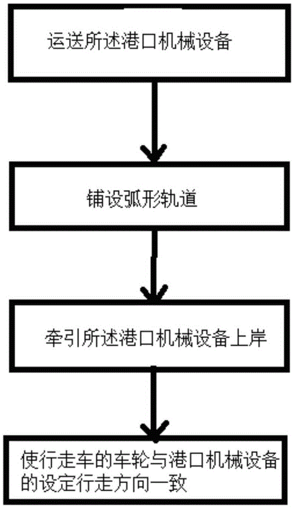
[0025] see figure 1 , the present invention provides a landing method for port machinery and equipment, comprising: step a, transporting the port machinery and equipment: fixing the port machinery and equipment on the delivery ship, making the delivery ship drive to the wharf, wherein the port machinery and equipment are driven by a walking vehicle located on the delivery ship Supporting, making the set walking direction of the wheels of the trolley intersect with the length direction of the delivery ship; step b, laying the arc track: making the two ends of the length direction of the arc track be located on the ground of the delivery ship and the wharf respect...


PUM


Abstract

The invention discloses a landing method for harbor mechanical equipment. The landing method comprises the steps that firstly, the harbor mechanical equipment is transported, wherein the harbor mechanical equipment is fixed to a transport vessel, the transport vessel travels to a harbor, the harbor mechanical equipment is supported by a walking trolley located on the transport vessel, and the set walking direction of wheels of the walking trolley and the length direction of the conveying vessel are crossed; secondly, an arc track is laid, wherein the two ends, in the length direction, of the arc track are located on the transport vessel and the ground of the harbor respectively, and the upper surface of the arc track forms an arc surface with a high middle and two low ends in the length direction; thirdly, the harbor mechanical equipment is pulled to be landed, wherein pulling equipment is used for pulling the harbor mechanical equipment to move towards the harbor from the transport vessel until the harbor mechanical equipment completely moves to the ground of the harbor, and the wheels of the walking trolley move on the arc track when the harbor mechanical equipment moves; fourthly, the set walking direction of the wheels of the walking trolley and the set walking direction of the harbor mechanical equipment are made consistent.

Description

technical field [0001] The invention relates to a method for transporting port mechanical equipment to a work site, in particular to a landing method for port mechanical equipment. Background technique [0002] The volume and weight of the ship loader as port mechanical equipment are relatively large, and with the optimization of the design, the weight of each structural part has been reduced a lot. The more common delivery method of the ship transfer machine in the prior art is to transfer the The various parts of the ship machine are transported to the wharf (worksite) in batches, but the structural strength of the ship loader in the prior art is no longer suitable for on-site hoisting and installation, because with the optimization of the design, the The stiffness is relatively low, and on-site assembly may damage these components due to buckling deformation of the components, and the batch delivery method in the prior art is also cumbersome and inefficient. [0003] In ...

Claims


Application Information

Patent Timeline
Patent Type & Authority Applications(China)
IPC IPC(8): B63B27/14
CPCB63B27/143
Inventor 李建光宋文亮吴健男
Owner CHINA SHENHUA ENERGY CO LTD
Learn More