Roller blind lifting device for vehicle and using method thereof

A lifting device and roller shutter technology, applied in vehicle parts, transportation and packaging, windows, etc., can solve the problem that the rack movement space is easy to interfere with the vehicle body, and achieve the effect of avoiding interference movement, compact structure, and shortened size.

Active Publication Date: 2017-09-19
HAIMEN CANGYUN MACHINERY CO LTD
View PDF9 Cites 0 Cited by
  • Summary
  • Abstract
  • Description
  • Claims
  • Application Information

AI Technical Summary

Problems solved by technology

In the prior art, an integrally solidified and connected rack is often used for driving the rack drive, which is likely to interfere with the car body in the movement space of the rack when it is close to the end of the car body

Method used


Image

  • Roller blind lifting device for vehicle and using method thereof
  • Roller blind lifting device for vehicle and using method thereof

Examples


Embodiment Construction

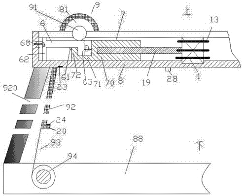
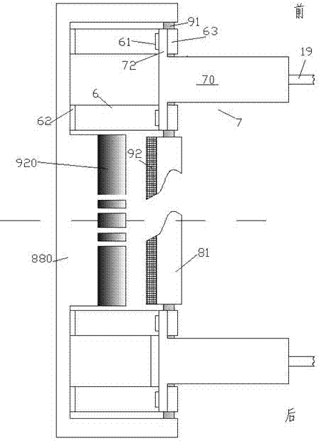
[0012] Combine below Figure 1-2 The present invention will be described in detail.

[0013] A roller blind lifting device for a vehicle according to an embodiment includes a fixed frame part 8 fixed on a vehicle body 88, and a roller blind assembly 9 pivotable relative to the fixed frame part 8, and the roller blind assembly 9 It includes a roller blind reel 81 that is fixedly connected to the upper end of the roller blind 92 and can wind the roller blind 92, a driving shaft gear 91 that is symmetrically coaxially arranged at the front and rear sides of the roller blind reel 81, and through The biasing pivoting wheel 94 that flexible pulling cable is fixedly connected with the lower end of described roller blind, described biasing pivoting wheel 94 is biased by pivoting biasing spring so that described roller blind 92 is pulled toward downward; Two rack drive assemblies symmetrically positioned on the front and rear sides of the roller blind reel 81 are arranged in the fixin...


PUM


Abstract

The invention discloses an automotive roller blind lifting device and a using method thereof, wherein the device comprises a fixing frame component (8) fixed on a vehicle body (88) and a roller blind component (9) capable of being pivoted relatively to the fixing frame component (8), the roller blind component (9) comprises a roller blind scroll (81) fixedly connected with the upper end of a roller blind (92) and capable of scrolling the roller blind (92), driving shaft type gears (91) symmetrically and coaxially arranged at the front side and rear side of the roller blind scroll (81) and a bias voltage pivoting wheel (94) fixedly connected with the lower end of the roller blind by a flexible pulling cable, and the bias voltage pivoting wheel (94) is biased by a pivoting bias spring, so that the roller blind (92) is tightly tightened downward; and the fixing frame component (8) is internally provided with two gear driving components symmetrically located at the front side and rear side of the roller blind scroll (81).

Description

technical field [0001] The invention relates to the field of vehicle window roller blinds, in particular to a vehicle roller blind lifting device and an application method thereof. Background technique [0002] Window roller blinds are used to adjustably shade windows and have been widely used in vehicles. [0003] It is usually considered to use a rack and pinion transmission mode to perform this adjustment in order to provide effective and reliable adjustment of the precise opening range of the curtain. [0004] However, due to the limited space of the vehicle and the aesthetics of the cabin, the overall size of the rack and pinion is expected to become smaller. In the prior art, an integrally solidified and connected rack is often used for drive in the rack drive, and when it is close to the end of the vehicle body, the movement space of the rack is likely to interfere with the vehicle body. Contents of the invention [0005] The object of the present invention is to ...

Claims


Application Information

Patent Timeline
Patent Type & Authority Patents(China)
IPC IPC(8): B60J1/20
CPCB60J1/2019
Inventor 杨婉珍
Owner HAIMEN CANGYUN MACHINERY CO LTD
Why Eureka
Try Eureka