
Automatic universal mold clamping mechanism for die casing machine or injection molding machine

A mold clamping mechanism and injection molding machine technology, applied in the field of die casting or injection molding equipment design and manufacture, can solve the problem of not being able to adjust at any time

Active Publication Date: 2016-05-11
张忠信
View PDF5 Cites 5 Cited by
  • Summary
  • Abstract
  • Description
  • Claims
  • Application Information

AI Technical Summary

Problems solved by technology

However, the universal mold clamping mechanism for die-casting machines or injection molding machines submitted by the above-mentioned applicant needs to be adjusted during the interval between equipment work when adjusting the parallelism between the moving template and the static template. In the above-mentioned non-parallel situation, adjustments cannot be made at any time

Method used


Image

  • Automatic universal mold clamping mechanism for die casing machine or injection molding machine
  • Automatic universal mold clamping mechanism for die casing machine or injection molding machine
  • Automatic universal mold clamping mechanism for die casing machine or injection molding machine

Examples


Embodiment Construction

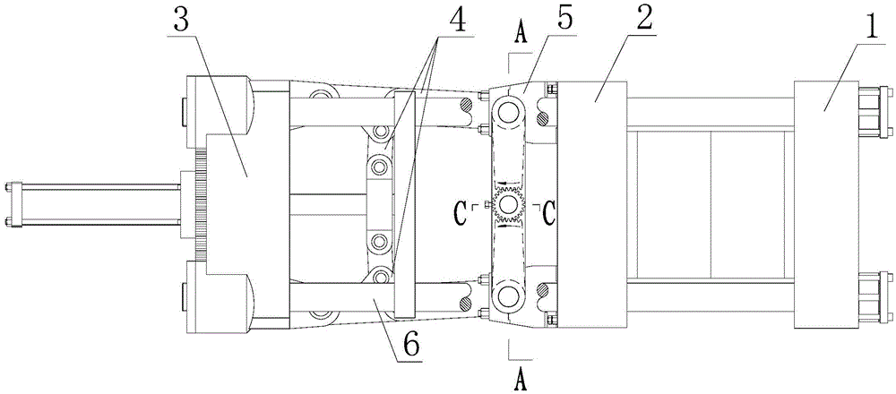
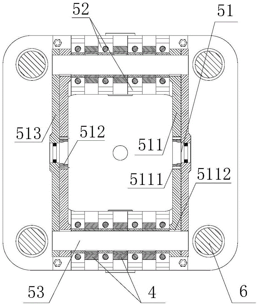
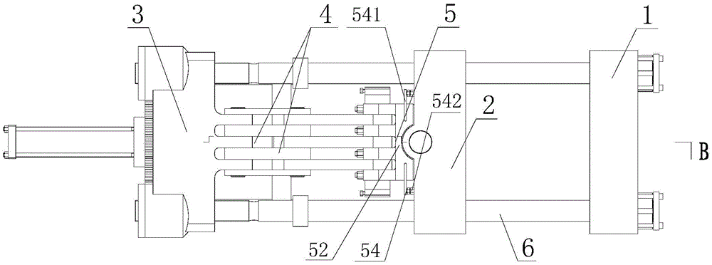
[0030] Such as Figure 1 to Figure 11 Shown is an automatic universal mold clamping mechanism for a die-casting machine or an injection molding machine provided by the present invention, which can effectively avoid inconsistent gaps between the movable mold plate and the static mold plate after mold clamping during the operation of the mold plate. The automatic universal mold clamping mechanism includes a static template 1, a movable template 2, a tail plate 3, a machine hinge 4 and a machine-hinge compound connection structure 5, and one end of the machine-hinge compound connection structure 5 passes through the machine hinge 4 Connected to the tail plate 3, the other end of the machine-hinged composite connection structure 5 is hinged to the movable template 2, and under the action of the driving force of the hinge, the movable template 2 is compositely connected through the hinge The cooperation between the structure 5 and the hinge 4 can move back and forth with respect to...


PUM


Abstract

The invention discloses an automatic universal mold clamping mechanism for a die casing machine or an injection molding machine and belongs to the field of die casting or injection molding equipment. The invention provides the automatic universal mold clamping mechanism in which an inconsistent gap is reserved between a moving mold plate and a fixed mold plate after a mold is clamped in the operation process of the mold plate, and the uniformity in stress is realized. The automatic universal mold clamping mechanism is characterized in that one end of a reamer composite connecting structure is connected with a tail board through a reamer, and the other end of the reamer composite connecting structure is hinged to the moving mold plate; the moving mold plate can reciprocate along the mold clamping direction relative to the fixed mold plate by matching the reamer composite connecting structure with the reamer; an automatic adjusting device for automatically adjusting the parallelism of the moving mold plate is arranged at one end, which is connected with the reamer, of the reamer composite connecting structure; the end, which is connected with the reamer, of the reamer composite connecting structure is movably connected with the reamer through the automatic adjusting device for automatically adjusting the parallelism of the moving mold plate; the parallelism of the moving mold plate in the operation process relative to the fixed mold plate is automatically adjusted and kept stable and consistent by the automatic adjusting device for automatically adjusting the parallelism of the moving mold plate in the working process.

Description

technical field [0001] The invention relates to an automatic universal mold clamping mechanism, in particular to an automatic universal mold clamping mechanism for a die-casting machine or an injection molding machine, and belongs to the technical field of die-casting or injection molding equipment design and manufacture. Background technique [0002] Molding equipment that realizes product molding by pressing molten materials into the cavity of a molding mold mainly includes die-casting machines for metal molding and injection molding machines for plastic molding, usually consisting of a mold clamping mechanism and its hydraulic transmission components, injection mechanism, electrical control components etc. [0003] The mold clamping mechanism is one of the main mechanisms in the die-casting machine and injection molding machine. It is mainly composed of a machine table, a moving template, a static template, a tail plate, a support bar, a mold opening and closing cylinder,...

Claims


Application Information

Patent Timeline
Patent Type & Authority Applications(China)
IPC IPC(8): B29C45/66B29C45/80B22D17/26
CPCB22D17/263B29C45/661B29C45/80B29C2945/76866
Inventor 张忠信
Owner 张忠信
Learn More